
Vpoint command in AutoCAD and the usage in details
1. The way to call Vpoint command in AutoCAD
| Scroll down menu | Screen menu | Type command | Tool bar |
| View » 3DView » Viewpoint | View 1 » Vpoint | Vpoint, Vp | View |
Vpoint command is to define view point to set up the view direction for 3D model following the view directions from front, from above, from left,… or the view directions of measuring axis projection.
Vpoint ¿
Current view direction: VIEWDIR=current
– Specify a view point or [Rotate] <display compass and tripod>: Enter coordinates of view point.
2. The options with Vpoint command in AutoCAD
- Specify a view Point
Enter coordinates (X, Y, Z) of view point to create the view direction of drawing from that view point.
Below is coordinate of view point corresponding to the view directions:
(0,-1,0) The projection from front – vertical projection.
(0,0,1) The projection from top – plan projection.
(-1,0,0) The projection from left – side projection.
(1,0,0) The projection from right – side projection.
(0,0,-1) The projection from bottom.
(0,1,0) The projection from back.
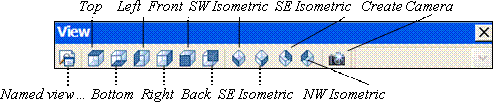
(-1,-1,1) The isometric perpendicular measuring axis projection (SW Isometric) corresponding to the axis system. (picture 1)
(1,-1,1) The isometric perpendicular measuring axis projection (SE Isometric) corresponding to the axis system. (picture 2)
(1,1,1) The isometric perpendicular measuring axis projection (NE Isometric) corresponding to the axis system. (picture 3)
(1,-1,1) The isometric perpendicular measuring axis projection (NW Isometric) corresponding to the axis system. (picture 4)

Vpoint command in AutoCAD and the usage in details
Rotate
This option defines new view point to create the view direction by using 2 angles. The first angle is matched with X axis in XY plane; the second angle is matched with XY plane.
Vpoint ¿
Current view direction: VIEWDIR = 1.0000, -1.0000, 1.0000
– Specify a view point or [Rotate] <display compass and tripod>: R¿
– Enter angle in XY plane from X axis <315>: 45 ¿ – Enter angle of view point which is matched with X axis in XY plane.
– Enter angle from XY plane <35>: 20 ¿ – Enter angle of view point which is matched with XY plane.

- Compass and Axis Tripod
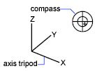
This option is activated when you press ENTER at the first line of Vpoint command. At this moment, compass and tripod are displayed (picture 1.8), here you can define the view direction in this viewport.
Compass is the flat performing image of globe surface. The center is on North Pole (0,0,n), inside round is Equator (n,n,0), it means XY plane, outside round is South Pole (0,0,-n).
You can move a small hair piece on compass to a position of globe by the pointer. When you move hair on compass, 3 axis x, y, z rotate suitably corresponding to the determined view direction on compass. To choose the view direction, you move the pointer to a position on compass then press the left of the mouse to choose.
Good luck!
Thanks for reading!!!
You can see more useful writings about CAD… here
You can see more commands in AutoCAD… here
If you find our work useful, your support would mean a lot and help us grow even better.DONATE
Related posts
UCSman command in AutoCAD – Manage the user coordinate systems
Distantlight command in AutoCAD – Create the distant light source
Lintype command in AutoCAD – Enter the linetypes in drawing
Hatch/Bhatch command in CAD
Dimradius command in CAD
Freeweb command in AutoCAD – Create the free weblight
Grid command in AutoCAD
Mtext command in CAD
Dimension Edit command in Autocad and the usage in details