

Sweep command in AutoCAD – Sweep to create 3D solid along to the path
Advertisements
Sweep command in AutoCAD – Sweep to create 3D solid along to the path
1. The way to call Sweep command in AutoCAD
| Screen menu | Type command | Tool bar |
| Draw 2 » Solids » Sweep | Sweep | Modeling |
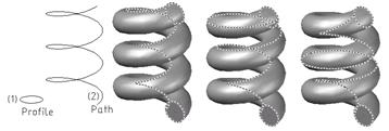
Sweep command is to create 3D models by sweeping the 2D flat curve which is close or open along a 2D, 3D close or open path. You can sweep many objects but all must be on the same plane.
– The objects can be swept as follows: Line, Arc, Elliptical arc, 2D polyline, 2D spline, Circle, Ellipse, Planar3D face, 2D solid, Traces, Region, Planar surface, planes of solid.
– The objects can be used as Sweep path as follows: Line, Arc, Elliptical arc, 2D polyline, 2D spline, Circle, Ellipse, 3D Spline, 3D Polyline, Helix, the edges of 3D object.
- Sweep
Current wire frame density: ISOLINES=4
Select objects to sweep: Select profile object to sweep (1).
Select objects to sweep: Continue to select object to sweep or press ENTER to complete.
Select sweep path or [Alignment/Base Point/Scale/Twist]: Select sweep path (2) to sweep or enter an option

Sweep command in AutoCAD – Sweep to create 3D solid along to the path
Note:
You can select the surfaces or the edges on solids or the surfaces by press and hold CTRL while you are selecting these objects.
The system variable DELOBJ can control the deleted profiles and sweep paths when the surfaces or solids are created, or you are reminded to delete the profiles and sweep paths. This variable can assign the following values:
All objects still exist.
- Profile curves are deleted when you use the commands: Extrude, Sweep, Revolve and Loft. The cross sections used by Loft command are also deleted.
- All deleted objects, including the paths and guide curves , are used by Sweep and Loft command
– The prompt line “delete profile curves” appears when you use the commands: Extrude, Sweep, Revolve and Loft. The cross sections used by Loft command are also deleted.
– The prompt line “delete objects” appears, including the paths and guide curves used by Sweep and Loft command.
You can choose the objects to sweep before starting the command.
2. The options with Sweep command
- Alignment
Profile is arranged to be perpendicular with tangent direction of the path or not. As default, profile is arranged to be perpendicular. When you enter A instead of the option, the following prompt line appears:
Align sweep object perpendicular to path before sweep [Yes/No] <Yes>: Enter Y to arrange, enter N to not arrange.
Sweep command in AutoCAD – Sweep to create 3D solid along to the path
- Note
If profile curve is not perpendicular with tangent of the start point of path curve, profile curve is automatically arranged. Enter No at the prompt line of Alignment to prevent this.
- Base Point
Define the base point for swept objects. If this defined point is not on the plane of the selected object, it is projected on this plane. When you enter B instead of the option, the following prompt line appears:
Specify base point: Specify a base point
- Scale
Enter scale factor for a sweep action. This scale factor is regularly applied for swept objects from the start point to the end point of the sweep path. When you enter S instead of the option, the following prompt line appears:
- Sweep
Current wire frame density: ISOLINES=4
Select objects to sweep: Select object (1) to sweep
Select objects to sweep:
Select sweep path or [Alignment/Base point/Scale/Twist]: S
Enter scale factor or [Reference] <1.0000>: 2 Enter scale factor or enter R
Select sweep path or [Alignment/Base Point/Scale/Twist]: Select the path (2) to sweep
 Scale factor =1 b) Scale factor =2")
Sweep command in AutoCAD – Sweep to create 3D solid along to the path
- Reference
Getting the scale of the selected objects basing on the length you reference by press to select the points or enter the value. When you enter R instead of the option, the following prompt line appears:
Specify start reference length <1.0000>: Enter the start reference length to get scale of the selected objects.
Specify end reference length <1.0000>: Enter the end reference length to get scale of the selected objects.
- Twist
Set up the twist angle for the swept objects. This twist angle defines the value of rotation angle following to whole length of sweep path. When you enter T instead of the option, the following prompt line appears:
- Sweep
Current wire frame density: ISOLINES=4
Select objects to sweep: Select object to sweep (1)
Select objects to sweep:
Select sweep path or [Alignment/Base point/Scale/Twist]: T
Enter twist angle or allow banking for a non-planar sweep path [Bank] <0.0000>: 90 Enter the value of twist angle <360
Select sweep path [Alignment/Base point/Scale/Twist]: Select the path to sweep (2);
Thanks for reading!!!
To know more tips, more errors and the other ways to correct error, you can continue to access CAD tips and refer more interesting things at our web
You can see more commands in AutoCAD… here
Advertisements