

504. CAD Drawings Detailing the Design of Water Supply and Drainage Systems for a 3-Story Townhouse
Advertisements
504. CAD Drawings Detailing the Design of Water Supply and Drainage Systems for a 3-Story Townhouse
The CAD drawings detailing the design of water supply and drainage systems for a 3-story townhouse provide an essential blueprint for architects and construction professionals. These drawings, composed of various technical illustrations, serve as a foundational tool in the construction process, ensuring effective planning and execution.
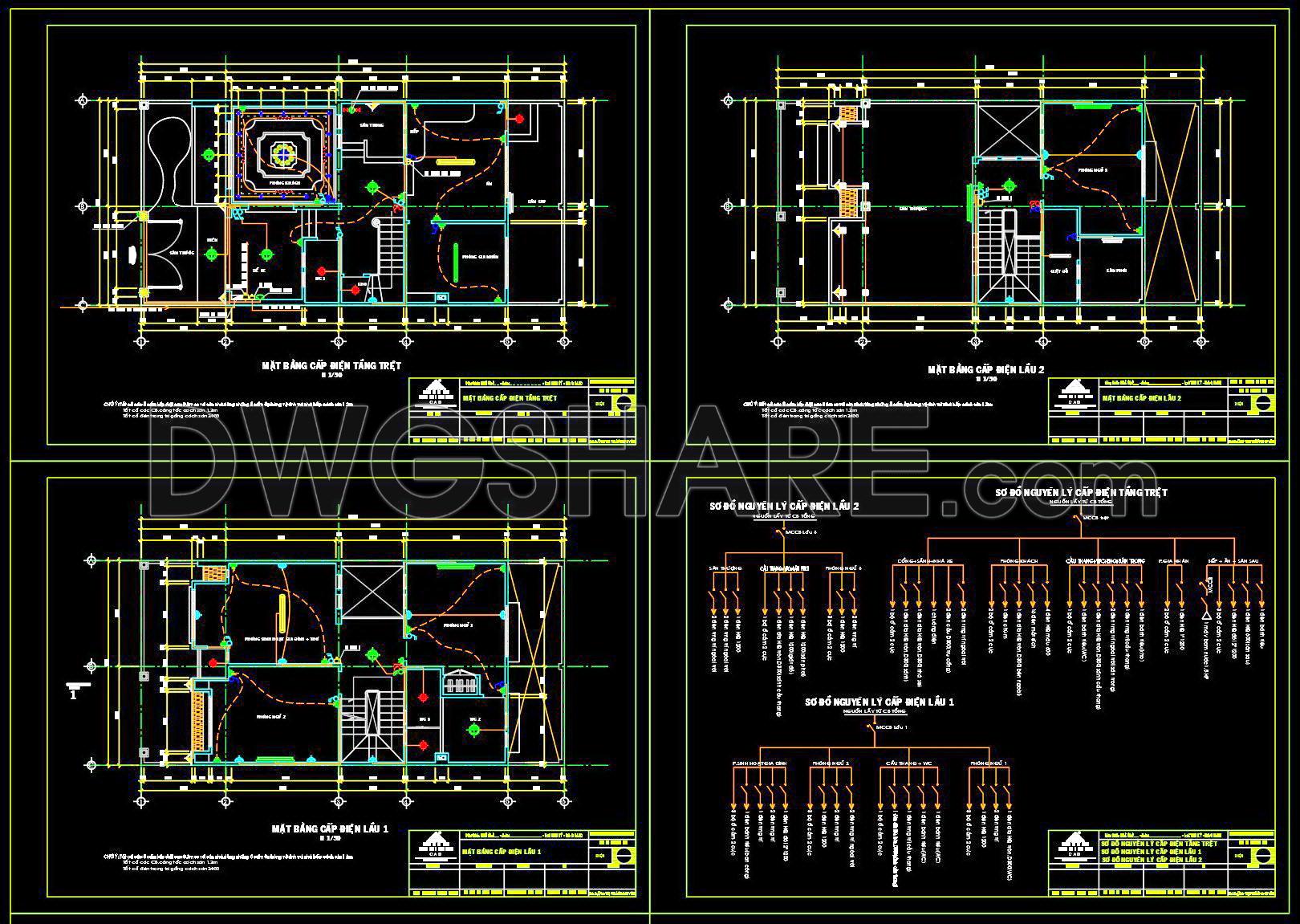
The key component of these drawings includes the combined water supply and drainage systems which are illustrated through detailed plans. These allow for a comprehensive understanding of the building’s plumbing infrastructure. The design includes functional layout, grid lines, and precise level markers, making the interpretation easier for professionals involved in the project.
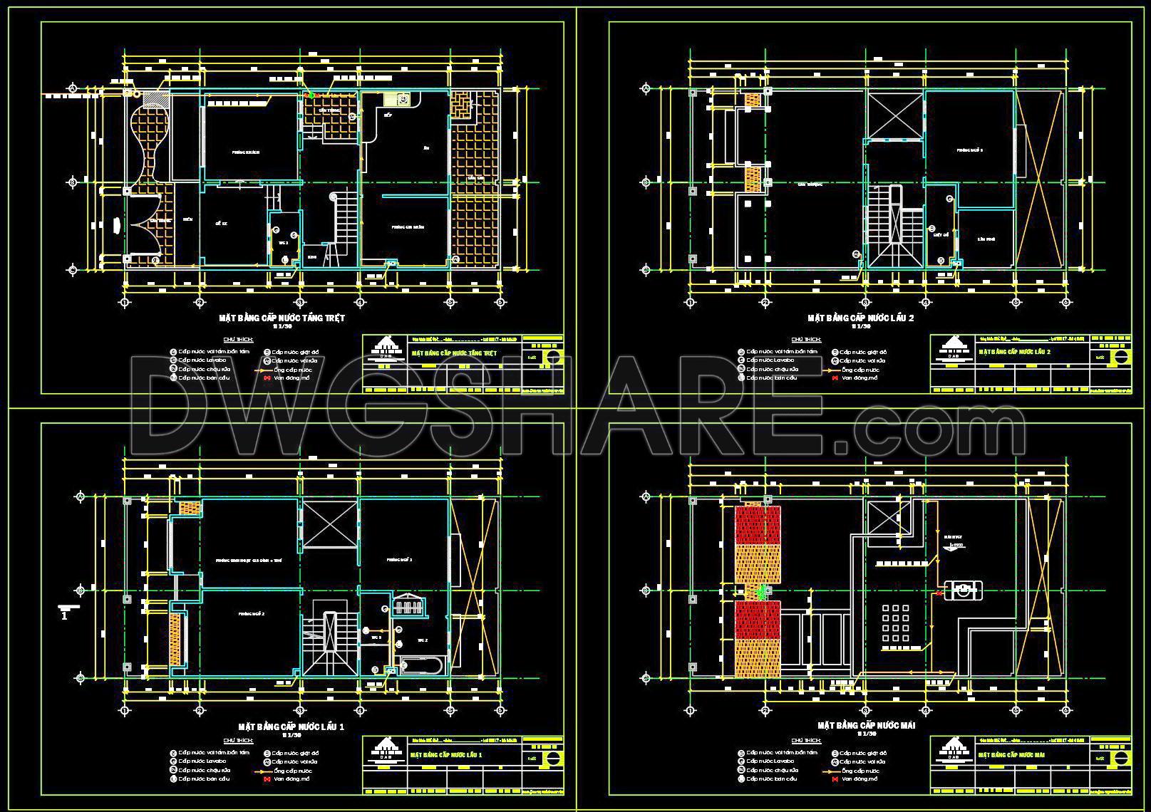
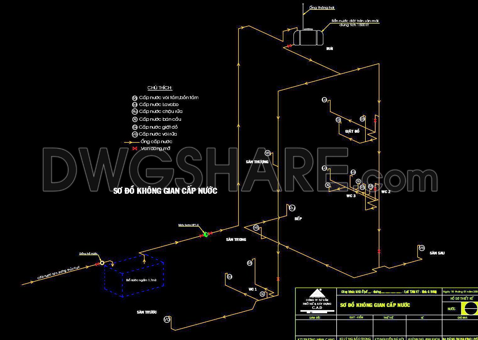
In the water supply system drawings, crucial elements such as pipes, valves, and tanks are clearly indicated. This system efficiently illustrates how water will be supplied across the townhouse, from the main water source to various facilities like kitchens and bathrooms. The use of a functional layout ensures that the water supply is streamlined across all stories, minimizing potential water wastage and maximizing utility.
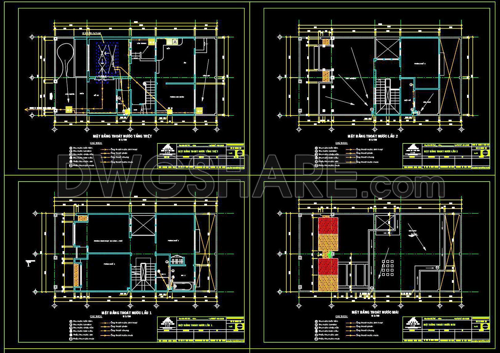
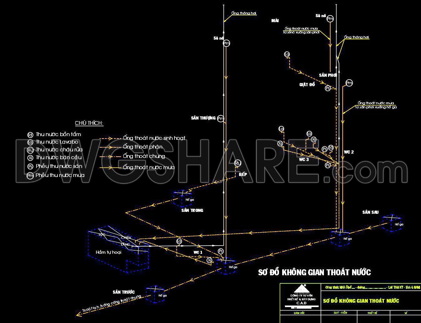
The drainage system drawings, on the other hand, detail how water and waste will be removed from the building. Elements such as the sewer connections, drainage pipes, and venting systems are meticulously charted out. This ensures optimal drainage flow, reduces risk of blockages, and prevents potential water damage.
Architects utilize these drawings during the initial design phase to ensure that both aesthetics and functionality are incorporated seamlessly. Interior designers benefit from these plans to integrate technical elements without compromising the design integrity. For construction teams, these drawings act as an invaluable reference, facilitating clear communication and coordination among team members, thus reducing errors and improving efficiency.
The practical value of these CAD drawings is immense. With high technical accuracy, they can be easily modified and reused in AutoCAD, promoting cost efficiency and minimizing labor. Moreover, these drawings improve overall coordination between design and construction teams, essential for successful project completion.
The CAD files are shared for free, making them an excellent resource for design reference, study, and research. They also serve as a base for further technical drawing development, catering to the needs of professionals looking to enhance their skills or adapt designs to varied specifications.
These detailed drawings are not merely blueprints but critical instruments that ensure the structural integrity and functional efficiency of modern architectural projects. By availing these resources, professionals can achieve a harmonious balance between cutting-edge design and practical construction needs, setting a benchmark in the housing industry.
I also recommend downloading other Mechanical, Electrical CAD drawings for your project reference.
- File format: .DWG
- Size: 510 KB
- Source: DWGshare
- AutoCAD platform 2018 and later versions. For downloading files there is no need to go through the registration process
Advertisements