

149. CAD drawings detailing the design of water supply and drainage systems for a 3-story townhouse
Advertisements
149. CAD drawings detailing the design of water supply and drainage systems for a 3-story townhouse
The CAD drawings detailing the design of water supply and drainage systems for a 3-story townhouse offer a comprehensive look into the intricate planning necessary for effective plumbing and water management in a modern residential structure. The drawings primarily consist of architectural floor plans and detailed sections which are essential for both the design and construction phases.
Key components visible in the drawings include:
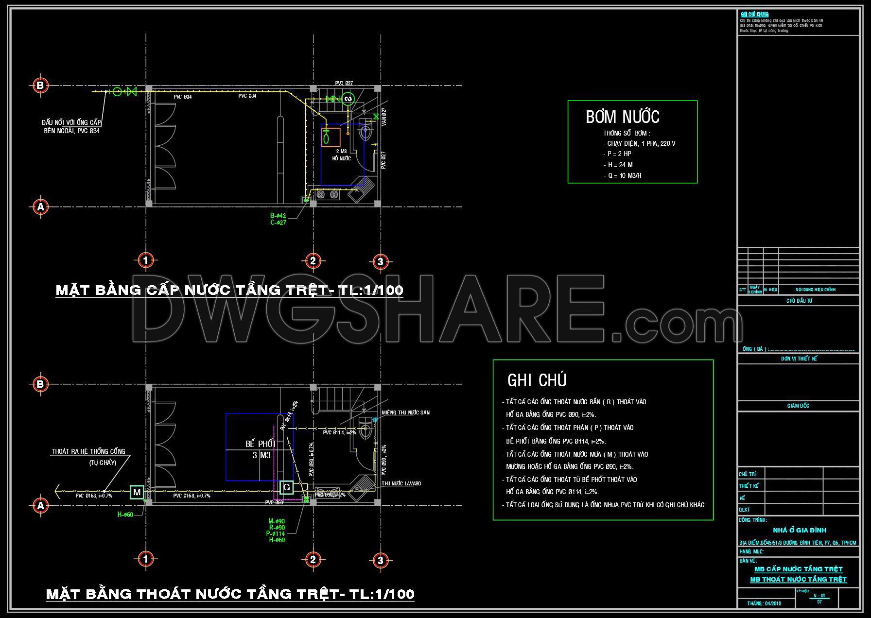
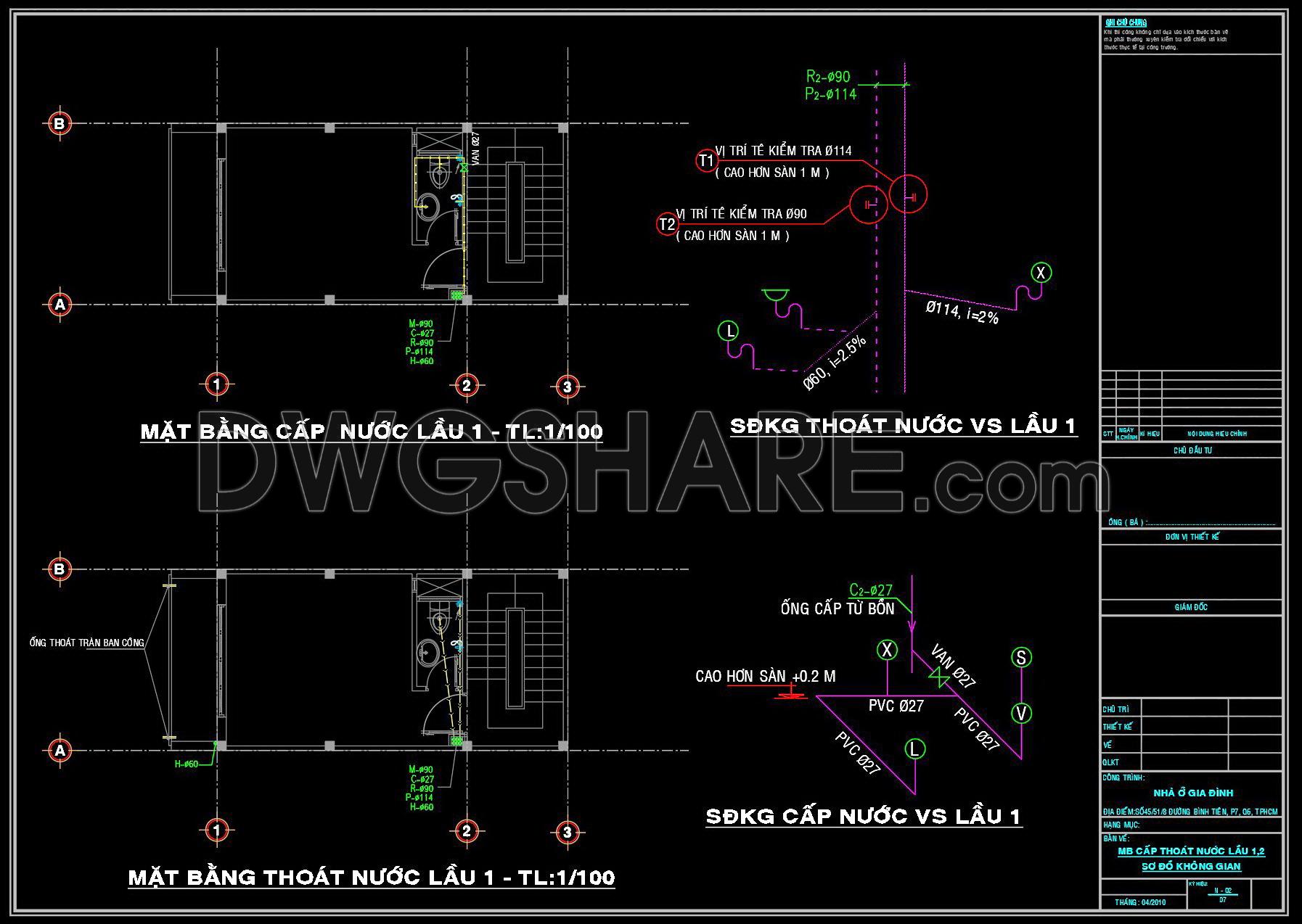
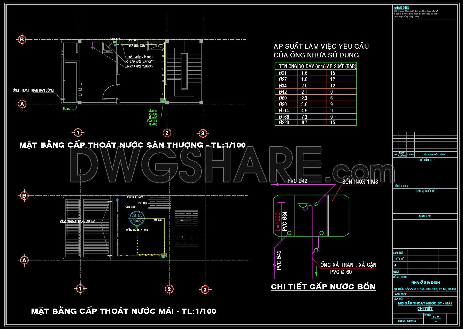
Floor plan layouts for water supply
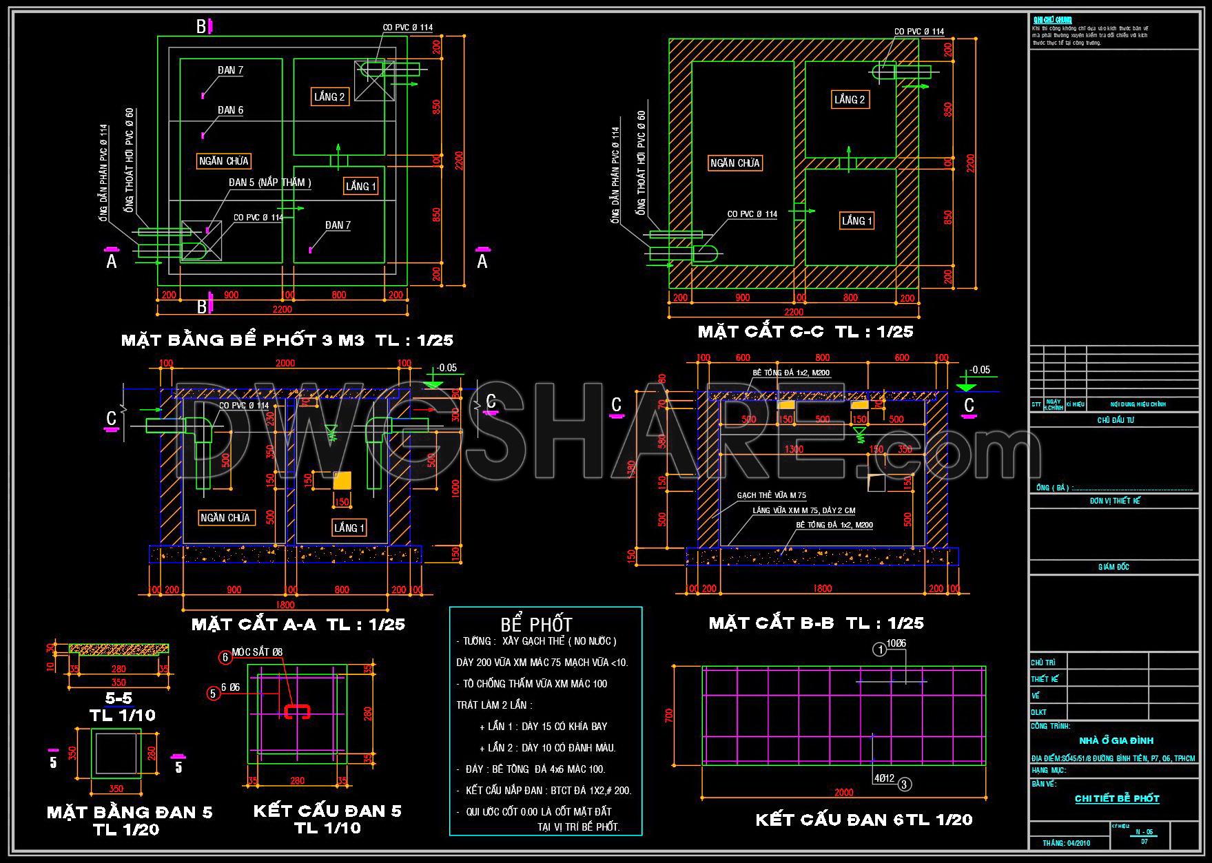
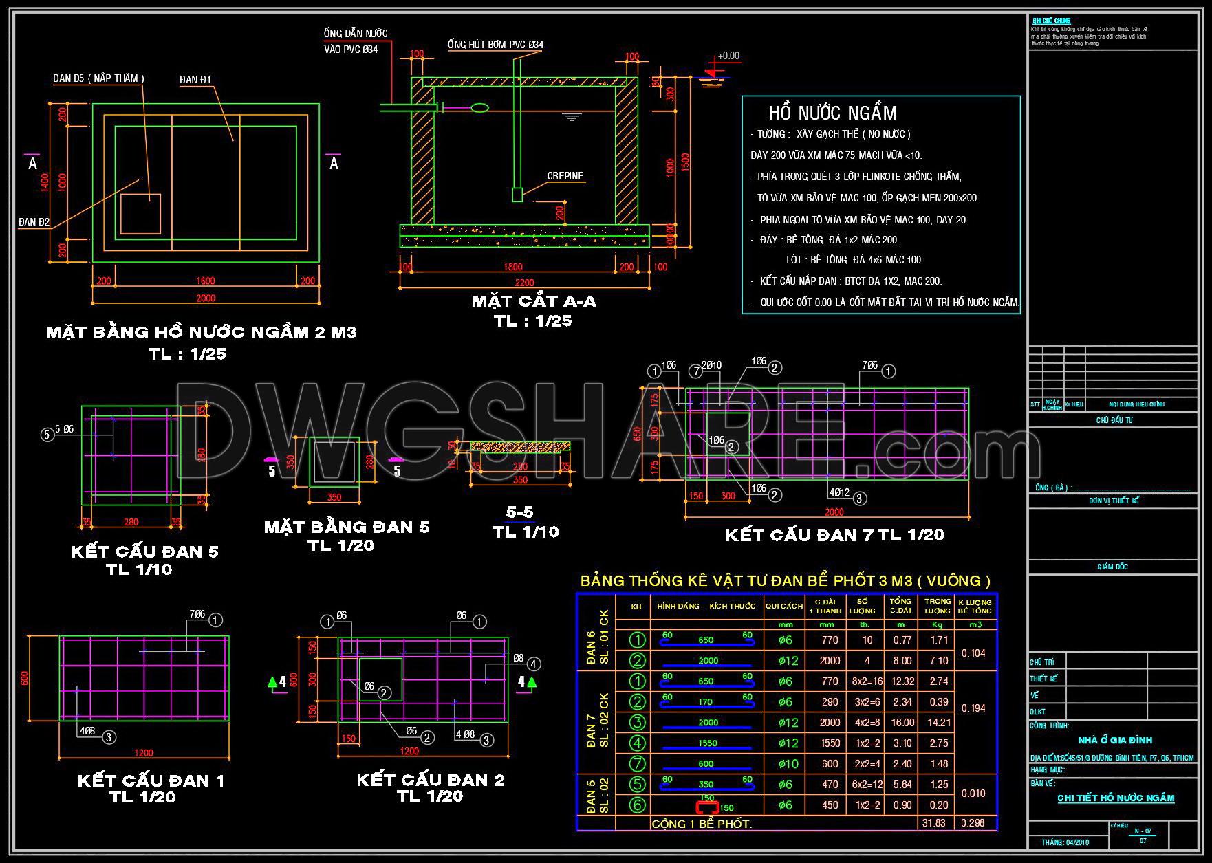
Detailed sections of drainage systems
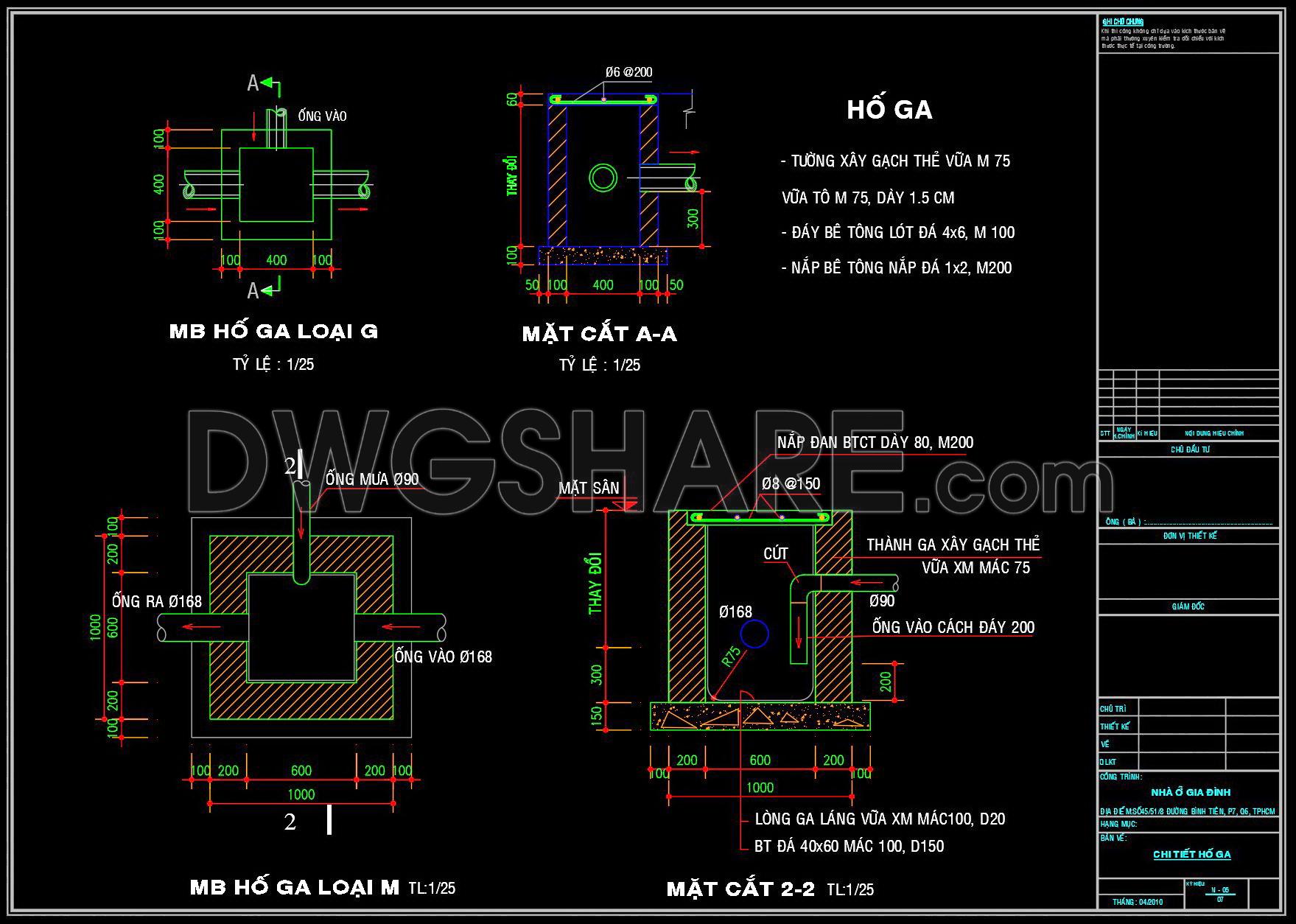
Construction details of manholes
Grid lines, dimensions, and level markers
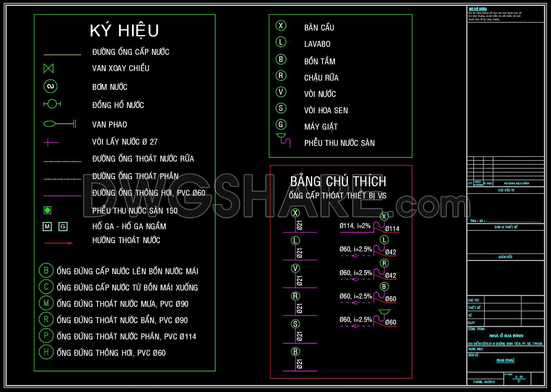
Plumbing symbols and legend
The floor plan layouts provide a clear depiction of how water is distributed throughout the townhouse across multiple levels. These plans are critical for architects and engineers who must ensure that the water systems are both efficient and sustainable. The layout shows how water is supplied to bathrooms, kitchens, and other utility areas, ensuring that consistent water pressure and flow rates are maintained.
Detailed sections included are particularly valuable, as they depict the complex routing of pipes, valves, and drains. These sections illustrate connections between different floors and highlight how gravity and pressure are manipulated for effective drainage. Construction teams rely heavily on these sections to ensure correct pipe installation, avoiding potential clogs or leaks that can lead to costly repairs.
Furthermore, the inclusion of construction details of manholes is a standout feature of these drawings. Manholes are integral to the maintenance and inspection of the drainage system. The drawings provide insights into their size, materials used, and method of construction, which are all critical for meeting municipal sewage regulations.
Architects and engineers also benefit from the grid lines and dimensions, which offer precise measurements and level markers crucial for accurate installation and alignment on site.
Plumbing symbols and a comprehensive legend are also present in these files, ensuring clear communication among professionals. This assists interior designers in refining the technical details within a space, ensuring that all design elements are cohesive and aligned with the necessary mechanical systems.
The CAD drawings demonstrate high technical accuracy and are easily modifiable within software like AutoCAD, allowing for adaptations as project requirements evolve. This flexibility leads to improved coordination between design and construction teams, significantly reducing the risk of errors and optimizing costs.
Available for free, these CAD DWG files serve as an excellent resource for anyone involved in architecture and urban planning. They are perfect for use as a design reference, academic study material, or as foundational templates to develop further technical drawings.
I also recommend downloading other Mechanical, Electrical CAD drawings for your project reference.
- File format: .DWG
- Size: 260 KB
- Source: DWGshare
- AutoCAD platform 2018 and later versions. For downloading files there is no need to go through the registration process
Advertisements