

689. Mechanical Escalator Elevation CAD Details DWG – Free Download
Advertisements
689. Mechanical Escalator Elevation CAD Details DWG – Free Download
The Mechanical Escalator Elevation CAD Details provided in these DWG files represent a crucial component in architectural and engineering projects. The detailed drawings encompass a comprehensive elevation view, showcasing the intricate construction and installation specifics of mechanical escalators, which are pivotal in enhancing the vertical movement within buildings.
The drawings include several essential components, such as:
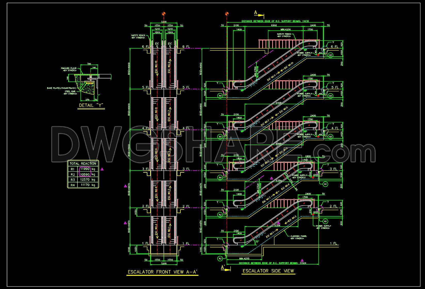
- Front View Elevations
- Side View Elevations
- Detail View for Component Installation
- Escalator Reaction Load Points
- Detailed Dimensions and Grid Lines
Initially, the front view elevation offers a clear, straightforward depiction of the escalator’s structural framework, illustrating the spatial arrangement and alignment within a building’s different floors. This view is invaluable for architects and engineers in understanding how the escalator integrates with overall architectural design and structural components.
The side view elevation is equally critical, revealing the escalator’s profile and providing insights into the mechanical and spatial considerations required for proper installation and functionality. The detailed dimensions shown ensure precision in placing the escalator accurately, accommodating necessary support structures.
Furthermore, the drawings contain a detailed view of component installation, allowing for effective planning and execution of installation processes. These specifics enable interior designers and architects to prepare comprehensive technical documents and ensure visual and structural harmony throughout the design.
The depiction of reaction load points is essential for construction teams, offering guidance on distributing weight and ensuring structural integrity. By incorporating detailed dimensions and grid lines, the CAD drawings provide architects with accurate scaling and measurement, reducing the likelihood of errors during construction and enhancing coordination across various project stages.
These CAD DWG files are high in technical accuracy and designed for easy modification and reuse in AutoCAD. As such, they become indispensable tools for reducing construction costs and optimizing structural design. The drawings are available for free download, making them an excellent resource for design reference, study, research, or as a foundational base for further technical development. These files ensure a seamless transition from design to practical application, effectively bridging the gap between concept and reality.
I also recommend downloading other Cad Details CAD drawings for your project reference.
- File format: .DWG
- Size: 136 KB
- Source: DWGshare
- AutoCAD platform 2018 and later versions. For downloading files there is no need to go through the registration process
Advertisements