

141. CAD drawings detailing the design of water supply and drainage systems for a 3-story townhouse
Advertisements
141. CAD drawings detailing the design of water supply and drainage systems for a 3-story townhouse
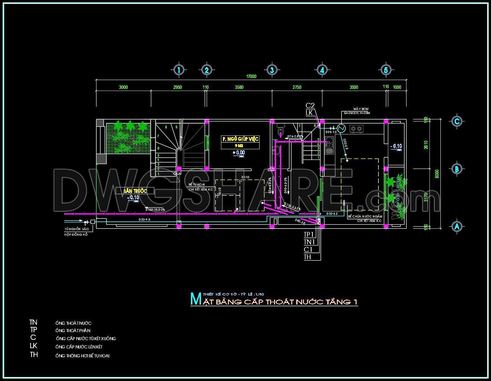
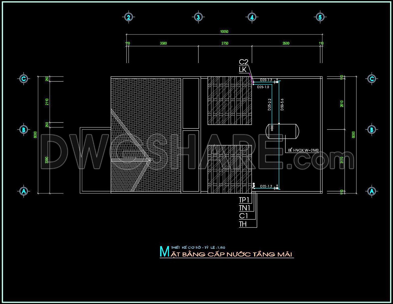
The CAD drawings detailing the design of water supply and drainage systems for a three-story townhouse are a remarkable resource for architects, interior designers, and construction teams. These technical drawings provide in-depth insights into the functional layout and structure of vital building services. Let’s delve into their components and significance in architectural and construction practices.
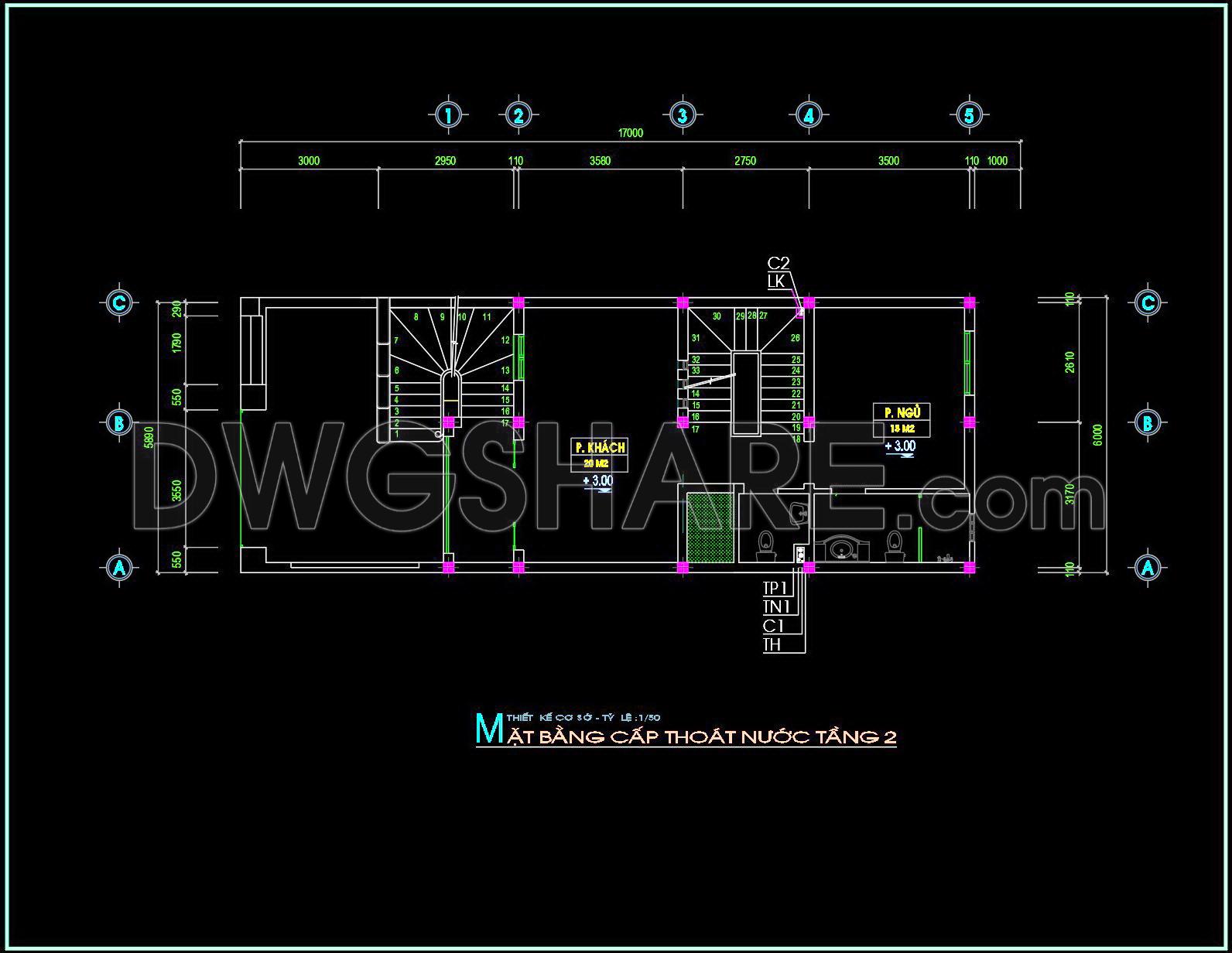
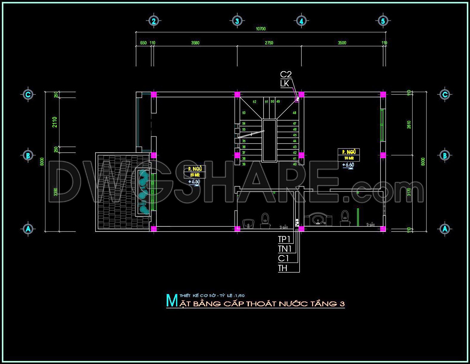
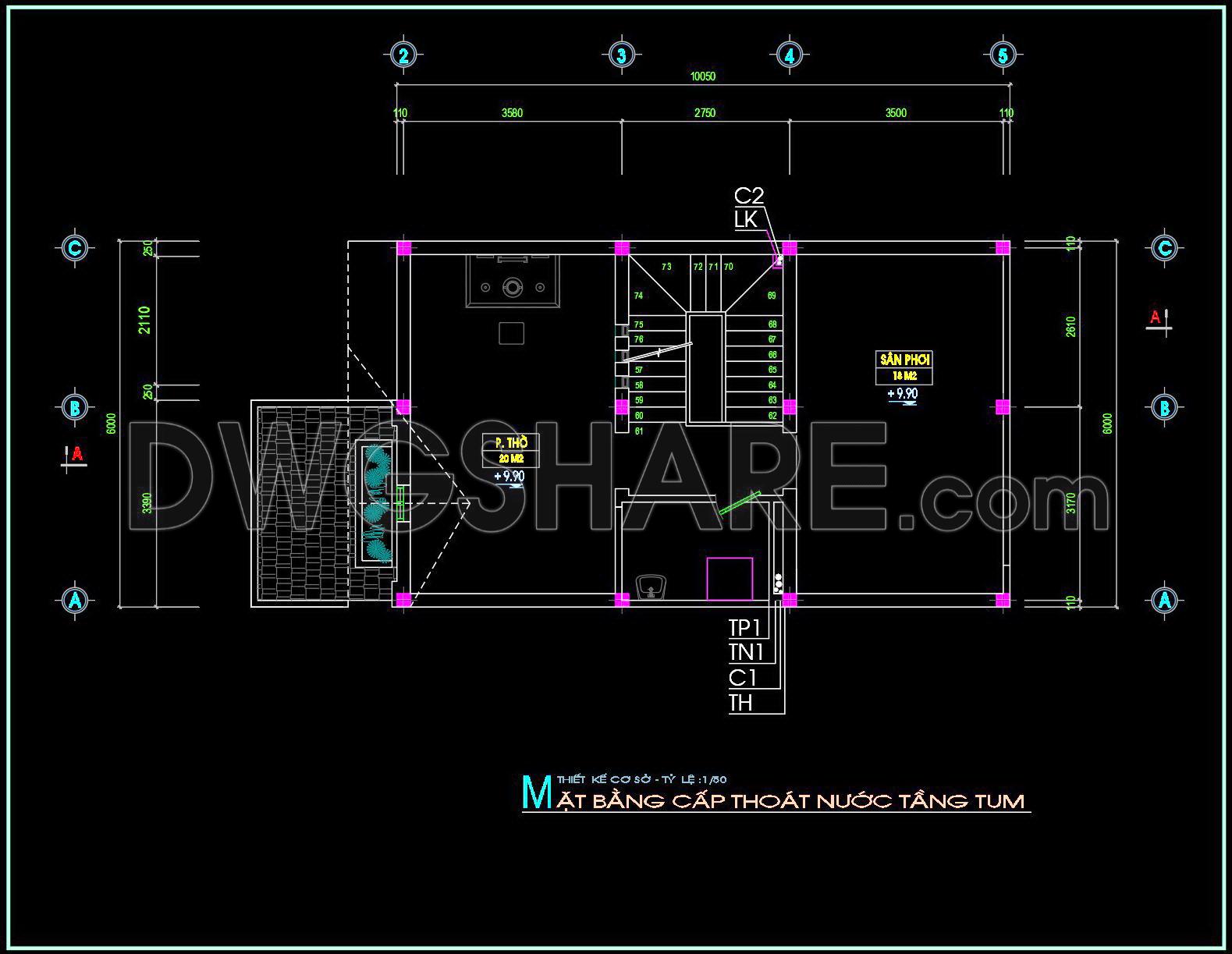
The first type of drawing is the functional floor plan layout. This layout is crucial for understanding the spatial arrangement and dimensions of different water supply and drainage elements. The drawings feature precise grid lines and dimensions, allowing for accurate placement and alignment of plumbing systems. Level markers indicate elevation details crucial for ensuring proper flow and pressure in the water supply system. By displaying the vertical and horizontal distribution of pipes, these layouts act as a blueprint for the installation process, ensuring that all systems are integrated seamlessly.
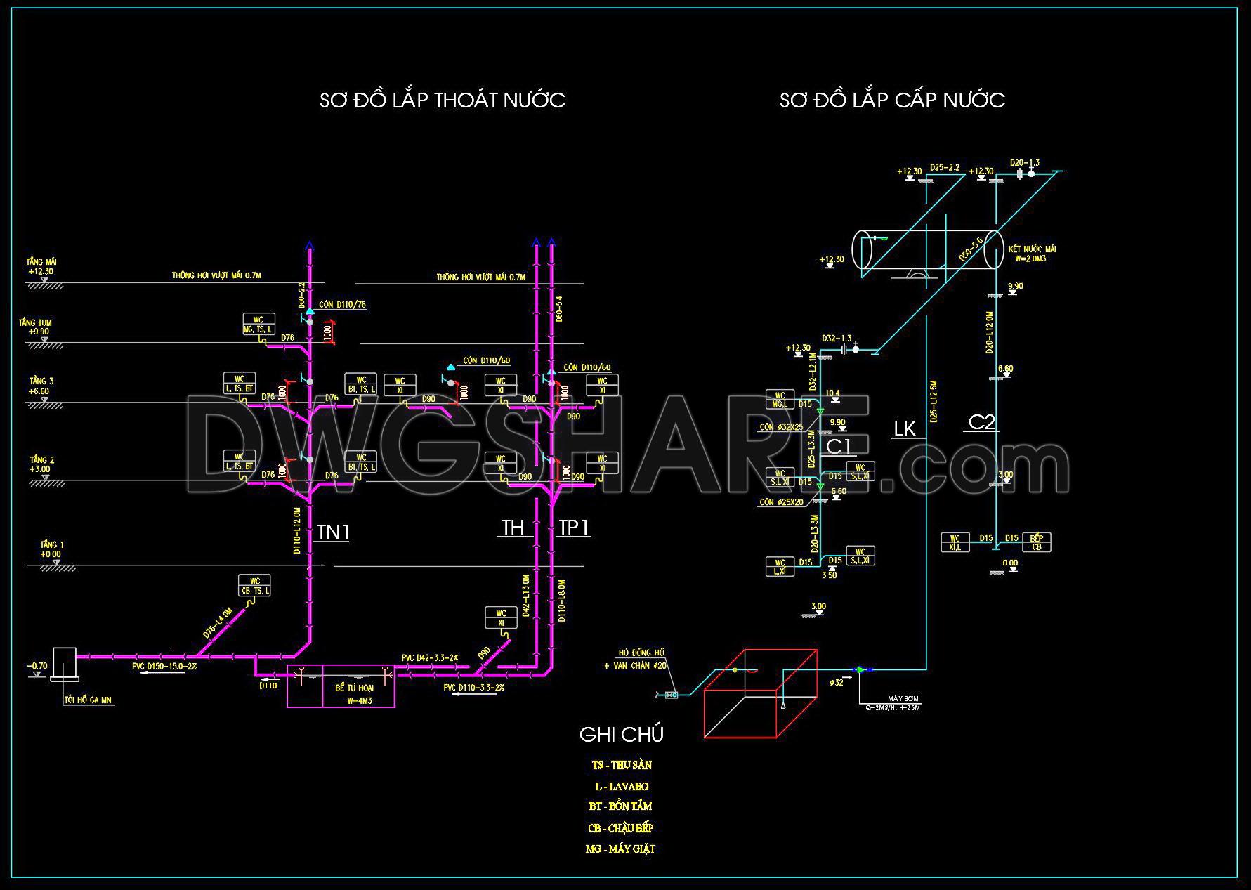
Next, the elevations and sections reveal the height and depth perspectives of the water supply and drainage structures. These views are essential for visualizing how various components such as pipes, inlets, and outlets intersect with architectural elements. The inclusion of such details provides a complete representation of how plumbing components are arranged vertically across all three floors. By understanding these relationships, construction teams can better plan for installation sequences and coordination, minimizing potential clashes with other structural elements.
The construction detail drawings are another vital component. They offer close-up views of specific junctions, joints, and other critical connections within the plumbing systems. These details guarantee that high technical accuracy is maintained, which is essential for preventing leaks or malfunctions. For interior designers, these drawings provide the technical specifications needed to plan interior layouts around existing plumbing installations, optimizing both space and design aesthetics.
In practical terms, these CAD drawings offer numerous benefits. Their high technical accuracy reduces errors during installation, leading to cost optimization and efficient project completion. The ability to easily modify and reuse these drawings in AutoCAD enhances design flexibility, allowing adjustments to be made swiftly in response to site conditions or client requests. By providing a shared point of reference, the drawings improve coordination between design and construction teams, ensuring a cohesive workflow from planning to execution.
Architects use these drawings to conduct design development, translating conceptual ideas into actionable construction plans. Interior designers refer to them when preparing technical detail layouts, ensuring that their designs accommodate necessary plumbing systems without compromising style. Construction teams rely on them for accurate installation guidance, promoting precision and efficiency.
These CAD DWG files are shared for free, making them an invaluable resource for design reference, study, and research. They serve as an excellent base for developing further technical drawing enhancements, offering industry professionals a robust foundation for future projects. By providing such comprehensive documentation, these CAD drawings play a fundamental role in ensuring the success of complex architectural ventures.
I also recommend downloading other Mechanical, Electrical CAD drawings for your project reference.
- File format: .DWG
- Size: 1 MB
- Source: DWGshare
- AutoCAD platform 2018 and later versions. For downloading files there is no need to go through the registration process
Advertisements