

318. CAD drawings for detailed electrical designs for a 3-story townhouse
Advertisements
318. CAD drawings for detailed electrical designs for a 3-story townhouse
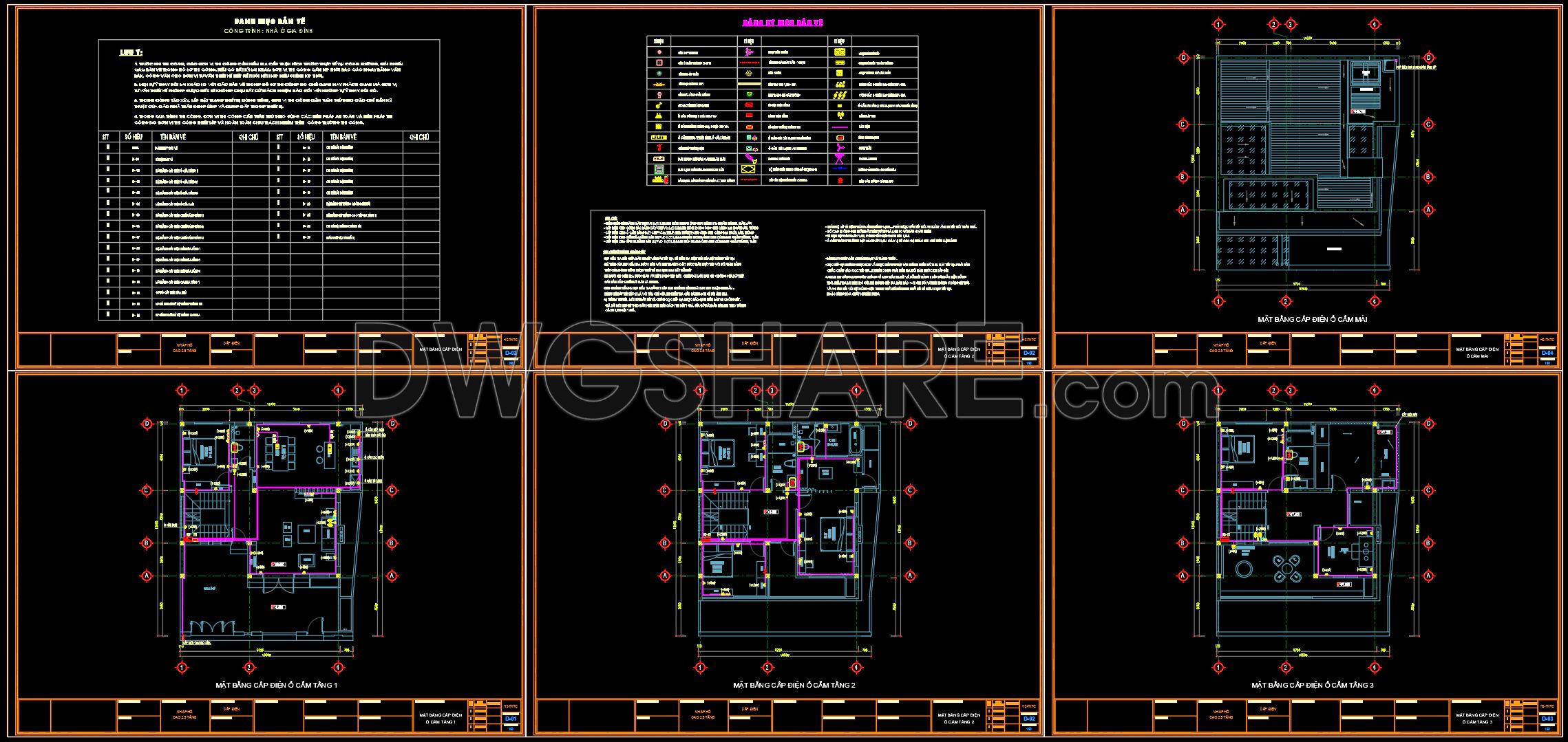
The detailed electrical CAD drawings for a three-story townhouse depict a comprehensive and meticulous electrical design, focusing on functional floor plan layouts, elevations, and construction detail drawings. These sophisticated visuals are pivotal for any architectural and construction team aiming for precision and efficiency in building projects.
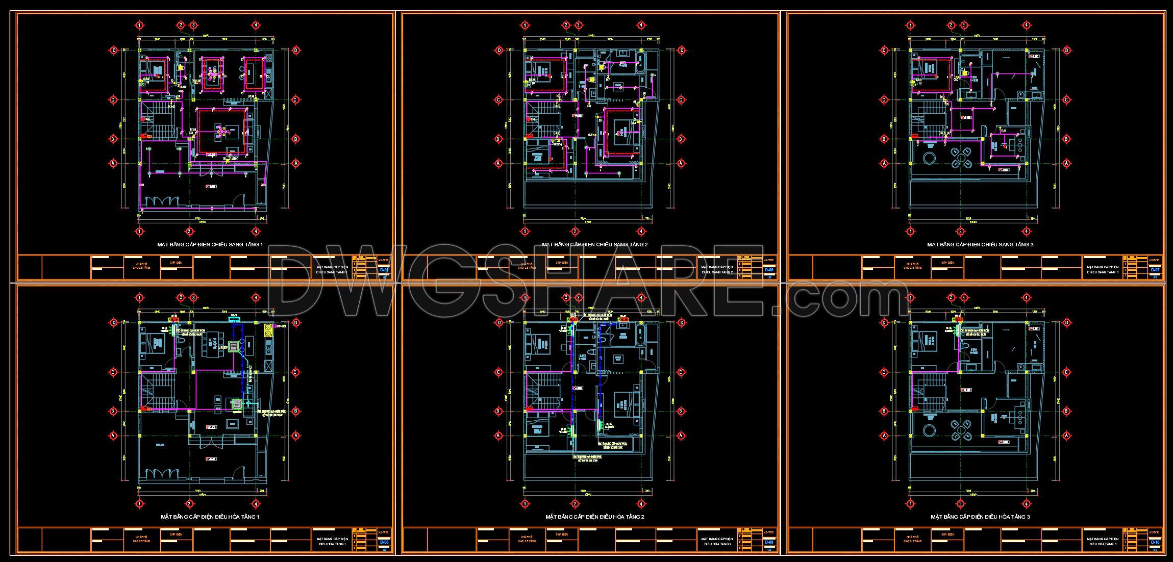
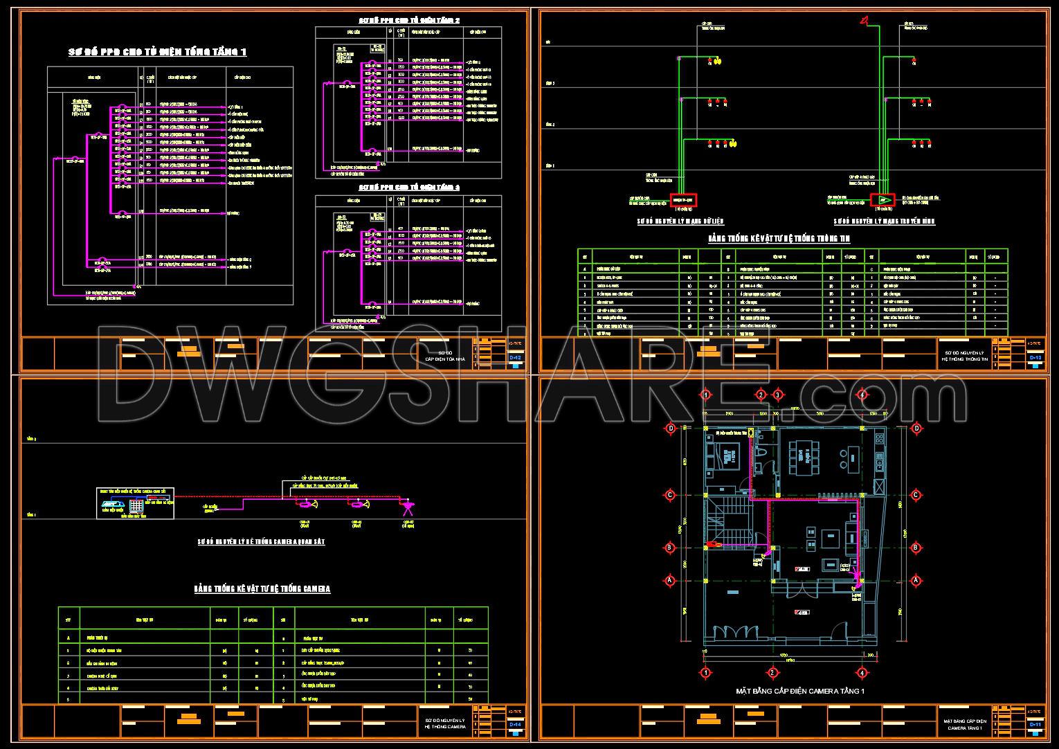
At the forefront are the functional floor plan layouts that provide architects with critical insights during the design development phase. These plans include lighting and electrical outlets, circuit diagrams, and distribution schemes across all three levels of the townhouse, essential for ensuring seamless electrical connectivity and safety.
The elevations and sections are central to these CAD drawings, offering vertical schematics that illustrate the placement and integration of electrical systems within the structural framework. Such views help architects visualize the spatial distribution and assist construction teams in ensuring that installations align with the architectural vision.
Construction detail drawings further contribute by highlighting specific aspects like junction boxes, cable routes, and control panels. These details are invaluable for achieving high technical accuracy and mitigating potential installation errors, reducing the likelihood of costly revisions.
Incorporated grid lines, dimensions, and level markers demonstrate a robust framework that aids architects, interior designers, and construction teams alike. For architects, these elements facilitate exact alignment and spatial planning. Interior designers benefit by using these specifics to craft aesthetically pleasing yet functional spaces, while construction teams rely on them for precise execution and coordination.
A notable practical advantage of these CAD drawings lies in their high technical accuracy, allowing for easy manipulation and reuse within AutoCAD software. This feature is instrumental in enhancing coordination between design and construction phases, leading to reduced errors and cost-efficient project outcomes.
The CAD DWG files are accessible for free, making them an ideal resource for design reference, academic research, or as a foundational base for developing advanced technical drawings. Their streamlined format and coherent presentation ensure that architects and designers can leverage them effectively to optimize both design creativity and construction implementation.
I also recommend downloading other Mechanical, Electrical CAD drawings for your project reference.
- File format: .DWG
- Size: 1 MB
- Source: DWGshare
- AutoCAD platform 2018 and later versions. For downloading files there is no need to go through the registration process
Advertisements