

678. Imhoff Tank Wastewater Treatment Section Details CAD Drawing
Advertisements
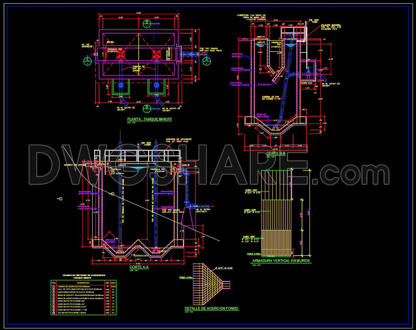
678. Imhoff Tank Wastewater Treatment Section Details CAD Drawing
The Imhoff Tank Wastewater Treatment Section Details CAD Drawing showcases essential plans and sections integral to the design and construction of an Imhoff tank structure. These architectural and structural drawings are meticulously crafted to guide professionals in developing efficient wastewater treatment solutions.
The drawing includes several vital components essential for the design development phase. A detailed functional floor plan layout is visible, highlighting the tank’s compartmentalization and spatial arrangement. This layout ensures that every section of the tank is optimally designed to facilitate the separation and settling of solids from wastewater. Elevations and sections provide a vertical perspective of the tank, illustrating the internal configurations and ensuring clarity in understanding how different parts of the structure relate in three dimensions. These views are crucial during both the design stage and construction, offering a comprehensive view of the tank’s dimensions, which are clearly marked with grid lines and level markers.
Additional construction detail drawings focus on the specific components such as the steel reinforcement within the foundation and walls of the tank. These details are indispensable when preparing for actual construction, ensuring that the strength specifications are met and that the integrity of the tank is maintained over time.
The technical precision inherent in these CAD drawings is of immense value to architects and construction teams alike. Architects utilize these drawings during the design development phase, allowing them to visualize and refine the tank’s layout and structural aspects. Interior designers, albeit less directly involved, might draw from these precise details when integrating such tanks into broader municipal or industrial designs. For construction teams, these drawings serve as the fundamental reference point during the building process. They assure compliance with design standards, facilitate accurate coordination of construction activities, and significantly minimize potential errors. This coordination leads to substantial cost optimization and efficiency gains, as accurate, editable, and reusable AutoCAD files reduce overall project timelines.
Available for free, these CAD DWG files are excellent resources for design reference and educational purposes. They offer an excellent starting point for further technical drawing development, ensuring that users can build upon a solid and well-documented foundation. By accommodating easy modifications, these files improve collaboration across different design and construction phases, facilitating seamless and effective project delivery.
I also recommend downloading other Uncategorized CAD drawings for your project reference.
- File format: .DWG
- Size: 1 MB
- Source: DWGshare
- AutoCAD platform 2018 and later versions. For downloading files there is no need to go through the registration process
Advertisements