

681. Rebar Lap Splice Length Details Based on ACI 318M CAD DWG
Advertisements
681. Rebar Lap Splice Length Details Based on ACI 318M CAD DWG
The Rebar Lap Splice Length Details Based on ACI 318M CAD DWG provides a detailed look into the crucial aspects of rebar connections as specified by the American Concrete Institute. This structural drawing is particularly relevant for civil and structural engineers tasked with ensuring the integrity and safety of reinforced concrete structures.
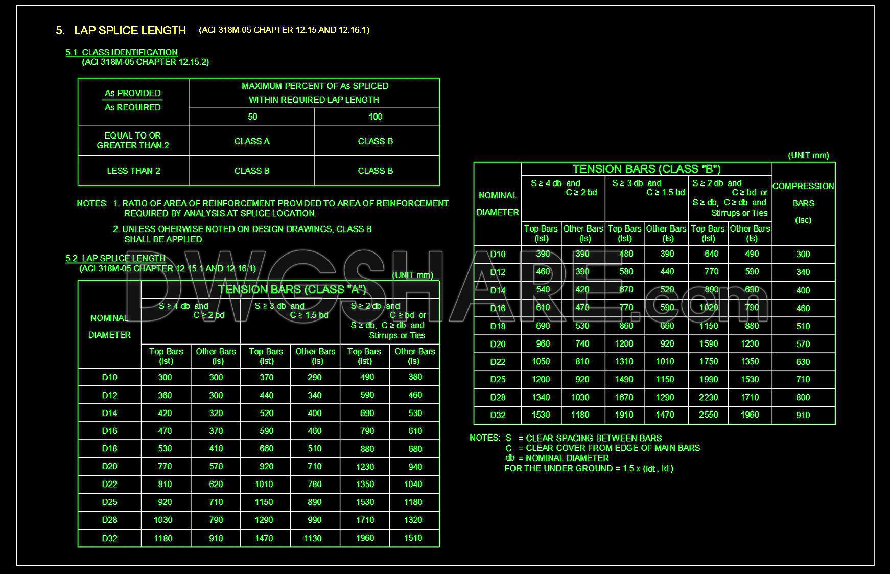
This technical drawing includes critical information on how reinforcement bars (rebar) should be spliced within a construction project, adhering to the standards set by ACI 318M. The drawing meticulously details the specific lengths required for lap splices, which are essential in transferring load and stress efficiently through the rebar network. This is particularly vital for maintaining the structural strength and durability of both small and large-scale projects.
The drawing is organized into sections that delineate various criteria and conditions for splice lengths. With detailed tables, the CAD file specifies nominal diameters, tension bars classification (Class A and B), and compression bars. The practical data allows engineers to quickly assess the necessary lap splice length based on the bar diameter and the specific class of tension bars being used. This precise information directly supports calculations for reinforcing elements, crucial for ensuring compliance with building codes and enhancing the integrity of building frameworks.
Construction professionals utilize this drawing for several purposes:
– Design Reference: By referencing precise dimensions and standards, engineers can ensure that designs are robust and adhere to stringent safety regulations.
– Construction Coordination: The drawing aids in the clear communication of specifications between architects, engineers, and construction teams, ensuring all parties are aligned on the required methods of connecting rebar.
– Cost Efficiency: By providing detailed splice information, the risk of errors is minimized, leading to reduced costs and material wastage during construction.
The CAD DWG files shared here are particularly useful as they allow for easy modification and reuse in AutoCAD software. This flexibility supports design development, allowing engineers to adjust plans efficiently based on site-specific conditions without compromising on accuracy or compliance.
Offering these files for free is a valuable resource for professionals seeking to enhance their understanding or for students aiming to study industry standards. They serve not only as a technical guide but also as a foundational tool in structural planning and analysis.
I also recommend downloading other Uncategorized CAD drawings for your project reference.
- File format: .DWG
- Size: 45 KB
- Source: DWGshare
- AutoCAD platform 2018 and later versions. For downloading files there is no need to go through the registration process
Advertisements