

717. Spillway Side Retaining Wall CAD Details DWG Download
Advertisements
717. Spillway Side Retaining Wall CAD Details DWG Download
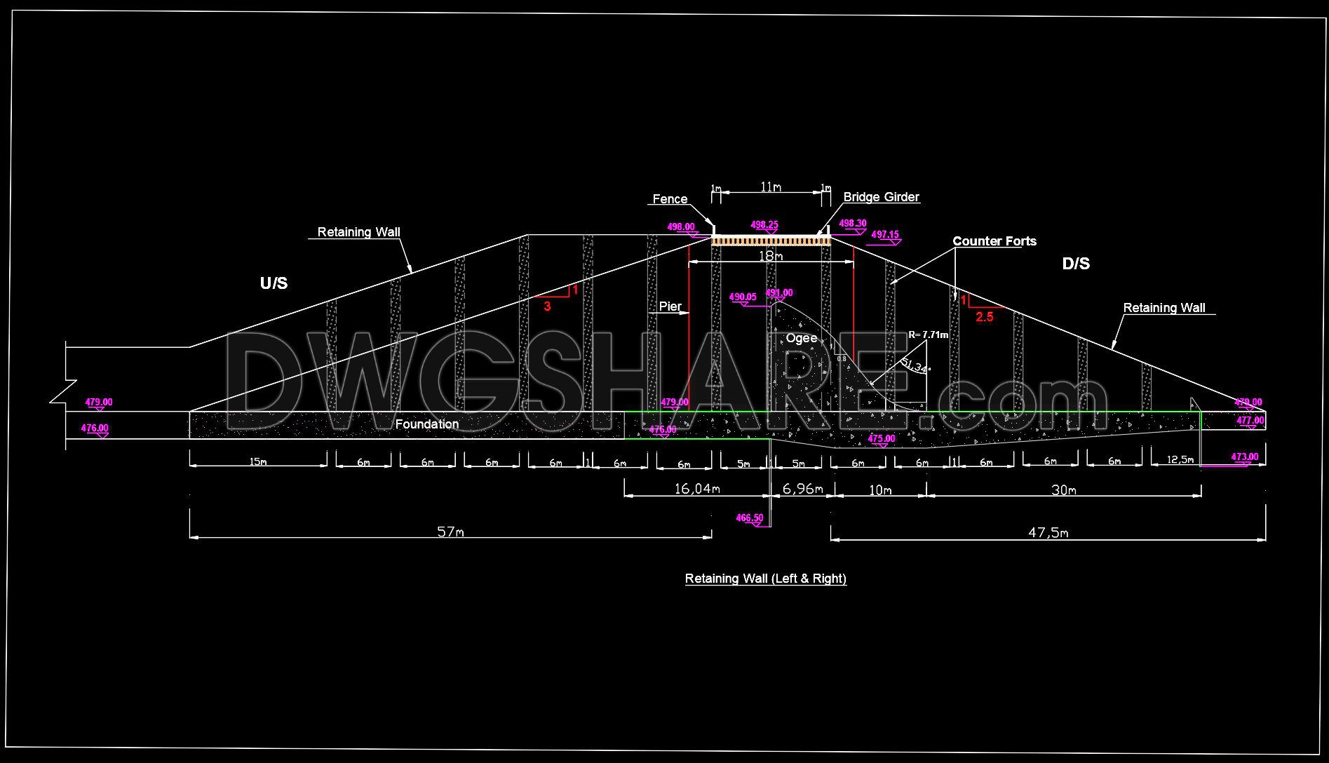
The spillway side retaining wall CAD details provide comprehensive structural drawings essential for the design and construction of retaining walls associated with spillways. These structural drawings are meticulously crafted to translate complex engineering requirements into precise visual documentation. Key components visible in these drawings include the foundational layout, the elevation of retaining walls, and specific detailing of piers and counterforts.
The drawings feature clear annotations such as grid lines, dimensions, and level markers, which are critical for ensuring accuracy in construction. Each section captures the essential structural aspects, helping architects and engineers visualize the interplay between different elements like the foundation, bridge girder, and ogee profiles. These details inform the necessary materials, methods, and technical specifications that will ensure the stability and functionality of the wall.
These files are indispensable for architects during the design development phase, enabling them to cross-reference and integrate structural components seamlessly. Interior designers and engineers benefit by using these drawings to prepare technical specifications and ensure that every detail aligns perfectly with the overarching design goals. For construction teams, these CAD files serve as a reliable guide for accurate execution, reducing errors and optimizing costs by ensuring every element is accounted for during the build phase.
The practical value of these drawings lies in their high technical accuracy and ease of modification in AutoCAD. This flexibility supports iterative design processes, allowing for quick revisions and adjustments as needed. As these files are shared freely, they serve as an invaluable resource for design reference, academic study, and further technical development, thereby enhancing collaboration and efficiency across the construction project lifecycle.
These CAD DWG files offer a robust foundation for constructing retaining walls, making them highly suitable for professionals seeking to optimize design and build processes. They empower professionals to ensure precision, foster better coordination between design and on-site execution, and ultimately achieve successful project outcomes.
I also recommend downloading other Cad Details CAD drawings for your project reference.
- File format: .DWG
- Size: 2 MB
- Source: DWGshare
- AutoCAD platform 2018 and later versions. For downloading files there is no need to go through the registration process
Advertisements