
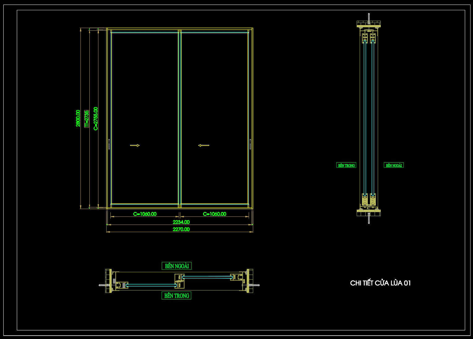
886. Sliding Glass Door CAD Drawing DWG – Elevation, Cross-Section and Installation Details
In the realm of architectural design and construction, precision and clarity are paramount. The Sliding Glass Door CAD Drawing DWG provides detailed insights into the design of sliding glass doors through its elevation, cross-section, and installation details. These drawings are crucial for architects, interior designers, and construction teams alike, ensuring that every element of the sliding door is meticulously planned and executed.
At the forefront of this CAD DWG is the elevation drawing, which presents a frontal view of the sliding glass door. This component is vital as it visually communicates the overall dimensions and aesthetic of the door, allowing architects to integrate the design seamlessly with the rest of the building’s facade. Key features such as panel dimensions and the overall width of the installation are clearly annotated, helping designers envisage the door within the larger context of their projects.
The cross-section drawing cuts through the sliding door, revealing internal components and structural details that are not visible in the elevation. This section is indispensable for interior designers and construction teams as it delineates the assembly of materials and the mechanical systems that enable the door’s operation. Details like track systems, frame support, and sealing methods are illustrated, providing a comprehensive understanding of how the door functions on a technical level.
Moving onto the installation details, these drawings provide a step-by-step guide on how the sliding glass door should be fitted. This includes precise measurements and alignment instructions that are crucial for achieving a flawless installation. Misalignment or improper fitting can compromise the door’s performance and the building’s energy efficiency. Therefore, these installation drawings are invaluable for construction teams, reducing the risk of error and avoiding costly reworks.
The practical application of these CAD drawings extends beyond immediate design needs. Architects utilize these files during design development to refine and optimize the door’s integration into their architectural plans. Interior designers refer to them while preparing technical details that complement the overall design aesthetic of interior spaces. Construction teams rely on these documents for reference and coordination, ensuring that every detail aligns with the design intent while adhering to safety standards.
A significant advantage of these CAD files is their high technical accuracy and flexibility. They can be easily modified and reused in AutoCAD, facilitating improved coordination between design and construction teams. This adaptability not only enhances the speed of project completion but also contributes to cost optimization by reducing material wastage and errors.
These CAD DWG files are shared for free, making them accessible resources for design reference, academic study, and as foundational bases for further technical drawing development. Their availability aids both seasoned professionals and students in mastering the art and science of architectural detailing.
I also recommend downloading other CAD detail drawings for your project reference.
- File format: .DWG
- Size: 116 KB
- Source: DWGshare
- AutoCAD platform 2018 and later versions. For downloading files there is no need to go through the registration process
If you find our work useful, your support would mean a lot and help us grow even better.DONATE
Related posts
433. Download free CAD drawings of detailed construction for a glass balustrade staircase
2.Cad Details Blocks free download
255. A detailed CAD drawing of the glass roof for the attic of a townhouse.
Detailed Drawings Of Living room In Autocad File
687. Utility Manhole and Handhole CAD Details DWG – Free Download
327. Detailed architectural CAD drawings of the balcony, railing, and skylight roof of the townhouse
70.Swimming Pool Full Detail Project AutoCAD Drawings
133. CAD drawings detailing the design of water supply and drainage systems for a 4-story townhouse
298. Detailed architectural CAD drawings of the facade townhouse