

166. Complete Residential Electrical, Lighting and Communication System CAD Drawings DWG
Advertisements
166. Complete Residential Electrical, Lighting and Communication System CAD Drawings DWG
The Complete Residential Electrical, Lighting and Communication System CAD Drawings offer an invaluable resource for architects and construction professionals. These drawings encompass a detailed set of electrical and communication schematics tailored for residential design, offering architects and builders an efficient framework for planning and execution.
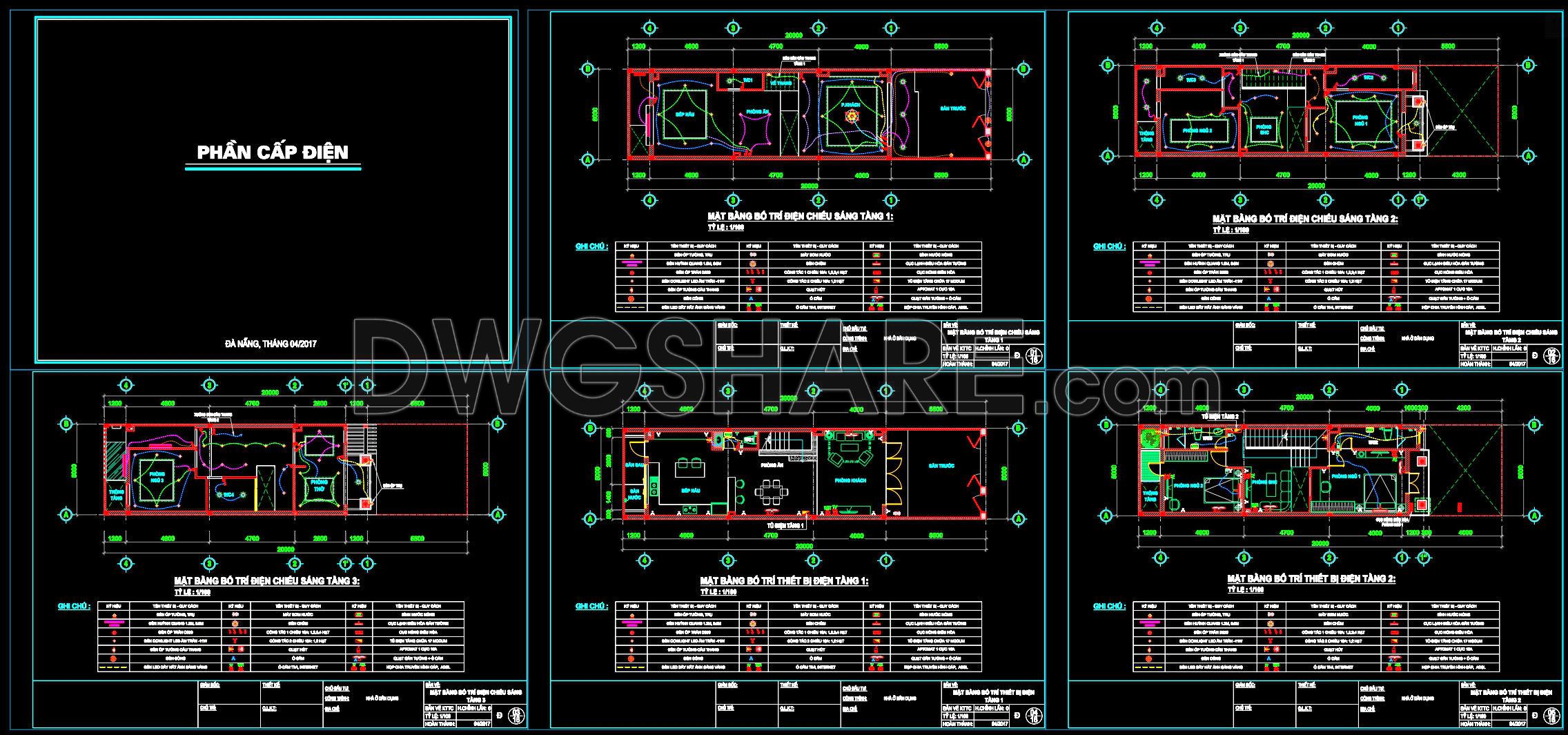
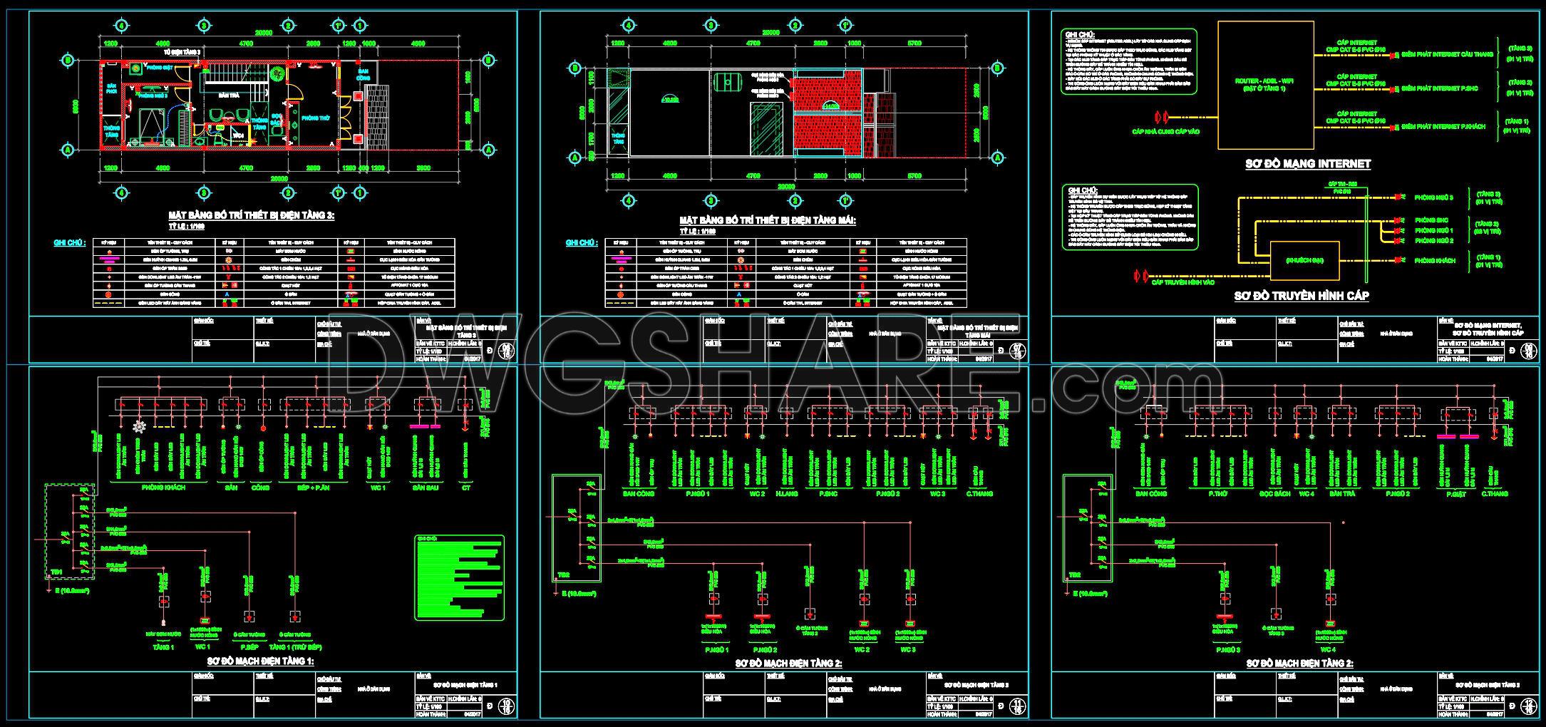
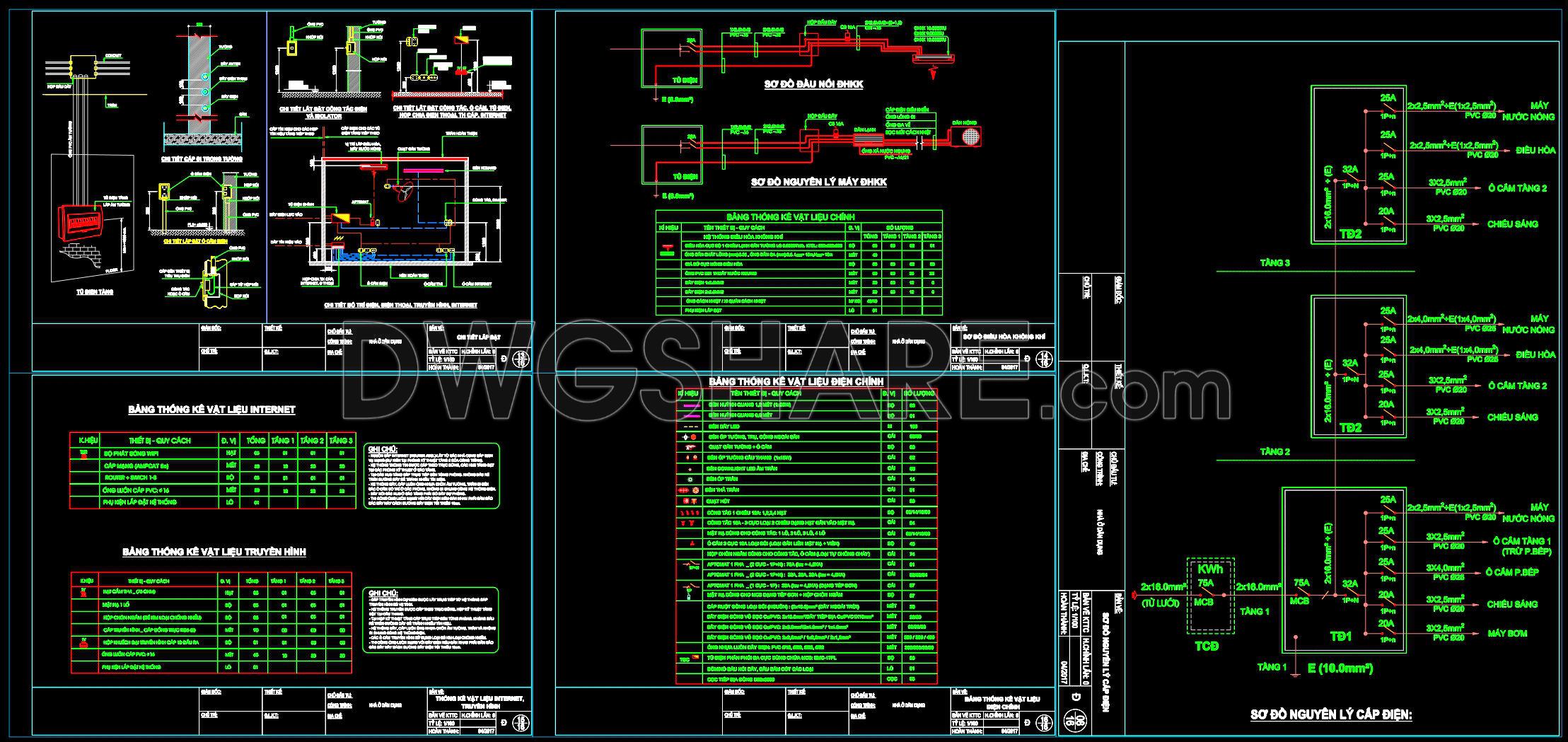
At the core, the electrical layout plans are meticulously designed to ensure functionality and safety. These include comprehensive setups for wiring circuits, cable paths, and panel schedules. With clear demarcations of grid lines and level markers, the plans facilitate precise execution on-site. These details are crucial for guiding electricians, ensuring that all residential units receive adequate power distribution without overloads.
Complementing the electrical layouts are the lighting plans, which meticulously detail the positioning and specifications of each lighting fixture. By incorporating scales and dimensional annotations, these plans allow architects to envision how lighting impacts the residential space, guiding interior designers and enhancing the aesthetic and functional lighting distribution.
Moreover, the set includes advanced communication system schematics. These charts illustrate the setup for internet, cable TV, and other essential home communication systems, pivotal for modern living environments. The role of these schematics is to ensure seamless integration of communication technologies, offering a structured approach to installing internet cables and satellite connections.
Each component is designed with high technical accuracy, promoting easy modifications and reuse in AutoCAD. This flexibility is a significant advantage, allowing architects to adapt designs to specific project needs while maintaining alignment between design proposals and construction realities. Such precision helps reduce errors and optimize costs, setting a strong foundation for effective project management.
The real benefit of these CAD drawings is their contribution to improved coordination between design and construction teams. By adhering to these structured diagrams, professionals can ensure that everyone speaks the same technical language, minimizing misunderstandings and inefficiencies.
These CAD DWG files are shared freely, a fantastic opportunity for design reference, study, and research. They offer a solid base for technical drawing development, allowing upcoming architects and seasoned professionals alike to explore and expand on pre-existing designs, providing infinite possibilities for architectural innovation.
I also recommend downloading other Mechanical, Electrical CAD drawings for your project reference.
- File format: .DWG
- Size: 1 MB
- Source: DWGshare
- AutoCAD platform 2018 and later versions. For downloading files there is no need to go through the registration process
Advertisements