

233. CAD Drawings of Kindergarten Fence and Gate (Plan, Elevations, Detailed Sections)
Advertisements
233. CAD Drawings of Kindergarten Fence and Gate (Plan, Elevations, Detailed Sections)
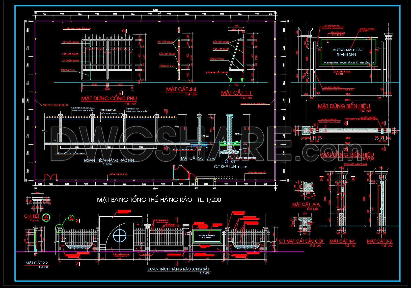
The CAD Drawings of Kindergarten Fence and Gate showcased here offer a meticulously detailed representation of essential architectural elements essential for the construction of secure and aesthetically pleasing kindergarten boundaries. These drawings encompass architectural floor plans, elevations, and detailed sections, each playing a crucial role in the comprehensive design and construction process.
The floor plan layout presents a clear overview of the fence and gate configuration, highlighting essential elements like gate placement, dimensions, and spacing. This provides architects with a functional schematic that is vital for initial design deliberations and ensures that the layout adheres to intended safety and aesthetic guidelines.
The elevations offer side views of the fence and gate design, revealing height specifications and the aesthetic characteristics of the materials used. They are instrumental for architects and designers to visualize the end product and ensure it complements the surrounding environment. Such detailed elevations assist interior designers and landscape architects in harmonizing design elements with other outdoor features, enhancing the overall visual coherence.
Detailed sections are included to illustrate cross-sectional views of the components. These construction detail drawings provide in-depth insights into materials, joinery, and structural supports, essential for construction teams during the building phase. The intricate detailing helps avoid miscommunication and errors during installations, ensuring that every component fits perfectly as designed.
The inclusion of grid lines, dimensions, and level markers in the drawings enhances technical accuracy, making them an excellent resource for engineering precision. The clarity of scale ensures that all stakeholders in the project — from architects to construction workers — have a shared understanding of measurements and spatial relationships.
In practical terms, these CAD drawings are invaluable due to their high technical accuracy and adaptability. They allow for easy modifications in AutoCAD, facilitating quick updates and refinements which are essential for iterative design processes. The capacity to be reused in future projects makes them cost-effective and reduces resource waste.
Available as free CAD DWG files, these drawings serve as an excellent reference tool for professional architects, designers, and students alike. They provide a reliable base for technical drawing development, design reference, or academic exploration, ultimately contributing to enhanced design accuracy, improved coordination between teams, and optimized construction costs.
I also recommend downloading other Educational building CAD drawings for your project reference.
- File format: .DWG
- Size: 194 KB
- Source: DWGshare
- AutoCAD platform 2018 and later versions. For downloading files there is no need to go through the registration process
Advertisements