

510. Fire Protection Piping Network Layout for High-Rise Buildings – AutoCAD DWG
Advertisements
510. Fire Protection Piping Network Layout for High-Rise Buildings – AutoCAD DWG
The Fire Protection Piping Network Layout for High-Rise Buildings CAD DWG files present a comprehensive set of diagrams crucial for modern building safety. These schematic drawings are meticulously crafted to display the intricate pipeline systems that serve an essential role in fire prevention and control within high-rise structures. The layout is a quintessential tool for architects, engineers, and construction professionals aiming to integrate effective fire protection systems that meet stringent safety regulations.
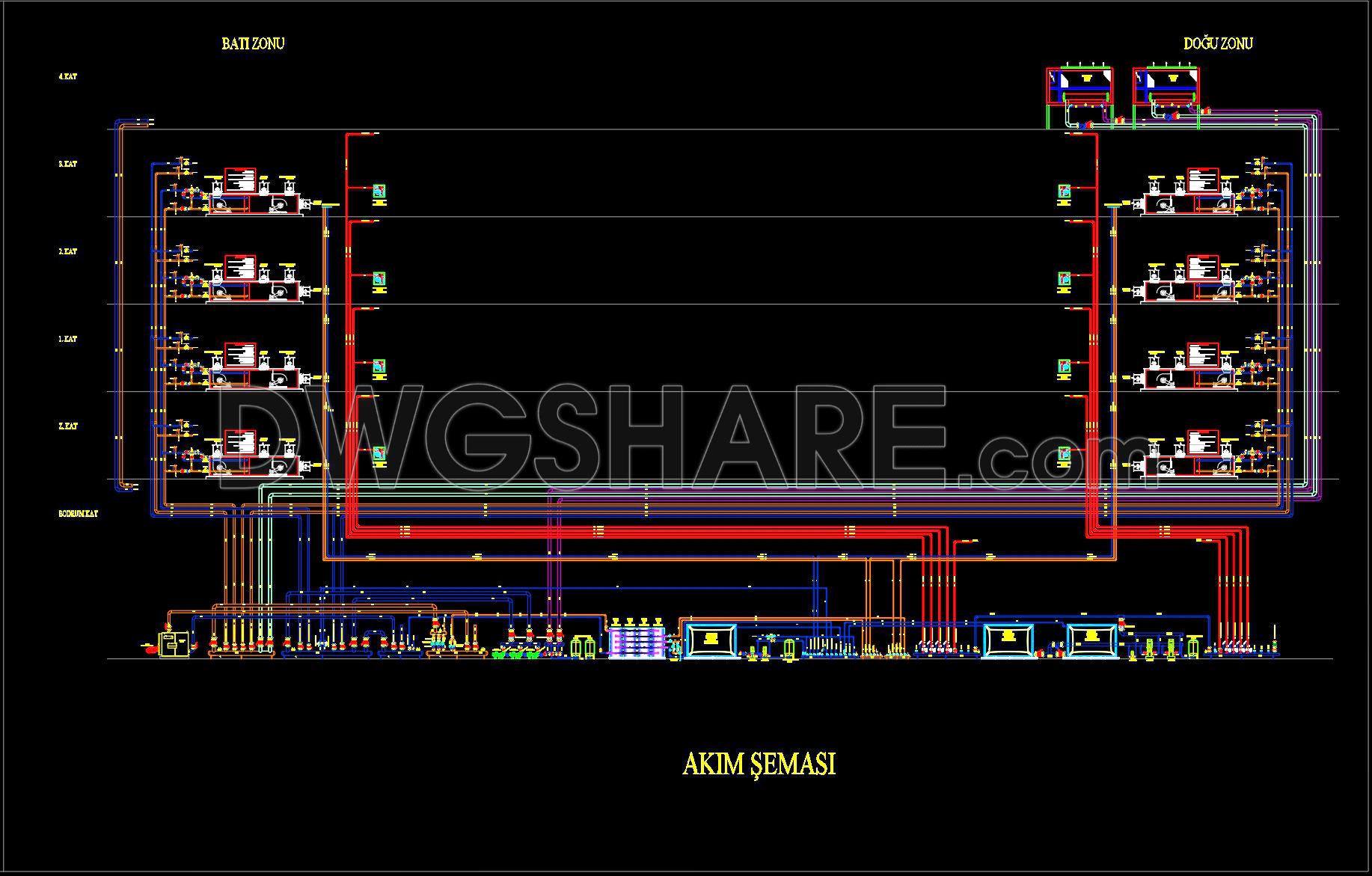
At the heart of these drawings is the flow diagram, a pivotal component represented with precision. This flow diagram provides a detailed visualization of the piping networks across multiple floors, illustrating how water is distributed throughout the building to key locations such as:
- Individual floor zones
- Basement and utility areas
- Vertical and horizontal pipe runs
Designed with high technical accuracy, the CAD drawings map out complex networks, highlighting critical features like grid lines, dimensions, and specific level markers that ensure each segment of piping is accurately placed. The clarity in these depictions aids architects during the design development phase, offering a clear reference for integrating the fire protection system seamlessly with other building systems.
Interior designers benefit from these drawings when preparing technical details that take into account aesthetic and spatial considerations around these necessary components. Meanwhile, construction teams rely heavily on this detailed documentation for reference and coordination, ensuring that installations are executed correctly and safely.
The drawings are engineered for easy modification, allowing users to adjust layouts to specific building requirements or local code changes efficiently. This adaptability reduces errors and minimizes costs, providing an excellent base for ongoing building design improvements.
These CAD DWG files are an invaluable resource, shared for free, and are well-suited for use as a design reference, facilitating study and research, or serving as a foundation for further technical drawing development. By offering accurate, reusable templates in AutoCAD, they significantly improve coordination between design and construction teams, promoting enhanced safety and efficiency in high-rise building projects.
I also recommend downloading other Mechanical, Electrical CAD drawings for your project reference.
- File format: .DWG
- Size: 2 MB
- Source: DWGshare
- AutoCAD platform 2018 and later versions. For downloading files there is no need to go through the registration process
Advertisements