

11. Guard House Architectural and Electrical CAD Drawing
Advertisements
11. Guard House Architectural and Electrical CAD Drawing
In the realm of architecture and construction, the Guard House Architectural and Electrical CAD Drawing offers a comprehensive insight into the design and practical application of this essential structure. These CAD drawings, presented in DWG format, provide detailed representations imperative for any construction or design team working on similar projects.
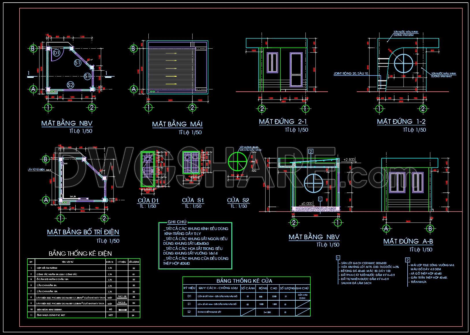
Starting with the Functional Floor Plan Layout, the drawings exhibit the spatial arrangement of the guard house, emphasizing efficient use of space to accommodate necessities like control panels, monitoring stations, and security checkpoints. The plan layout is meticulously organized with clear dimensions, ensuring accurate interpretation by construction teams.
The Elevations and Sections are integral components within these CAD files, offering precise vertical depictions of the guard house’s facade and cross-sections. These aspects are crucial for understanding the architectural aesthetics and structural elements, helping architects and designers ensure consistency in style and material application across the project.
Notably, the Construction Detail Drawings highlight essential build specifications. These drawings include intricate details of doors and window placements, which are pivotal for contractors during the assembly phase. The level of clarity in detailing aids in reducing miscommunications on the construction site, ultimately improving project efficiency.
Additionally, the CAD drawings feature Grid Lines, Dimensions, and Level Markers, which underpin the entire design’s structural integrity. Accurate plotting of these elements facilitates precise construction, ensuring that every segment aligns perfectly during physical assembly.
The practical utility of these CAD drawings is manifold. Architects benefit by refining their designs during the developmental phase, while interior designers use them to understand space interactions and prepare detailed decoration plans. Meanwhile, construction teams rely heavily on these drawings for accurate execution and coordination, minimizing errors and optimizing costs.
The technical accuracy in these CAD drawings stands out as they allow easy modification and adaptation within AutoCAD, making them reusable for future projects. This adaptability enhances coordination between the design and construction phases, fostering a seamless workflow from start to finish.
Available as a free resource, these files are invaluable for design references and offer an excellent foundation for study and research or the development of further technical drawings. They represent a practical toolkit for any professional seeking to enhance the efficiency and safety of built environments.
I also recommend downloading other Guard house CAD drawings for your project reference.
- File format: .DWG
- Size: 168 KB
- Source: DWGshare
- AutoCAD platform 2018 and later versions. For downloading files there is no need to go through the registration process
Advertisements