

12. Guard House Structural and Architectural CAD Drawings
Advertisements
12. Guard House Structural and Architectural CAD Drawings
The Guard House Structural and Architectural CAD Drawings provide a comprehensive insight into the design and construction elements crucial for security structures. These CAD files offer a detailed representation of various components essential for both architectural and structural planning.
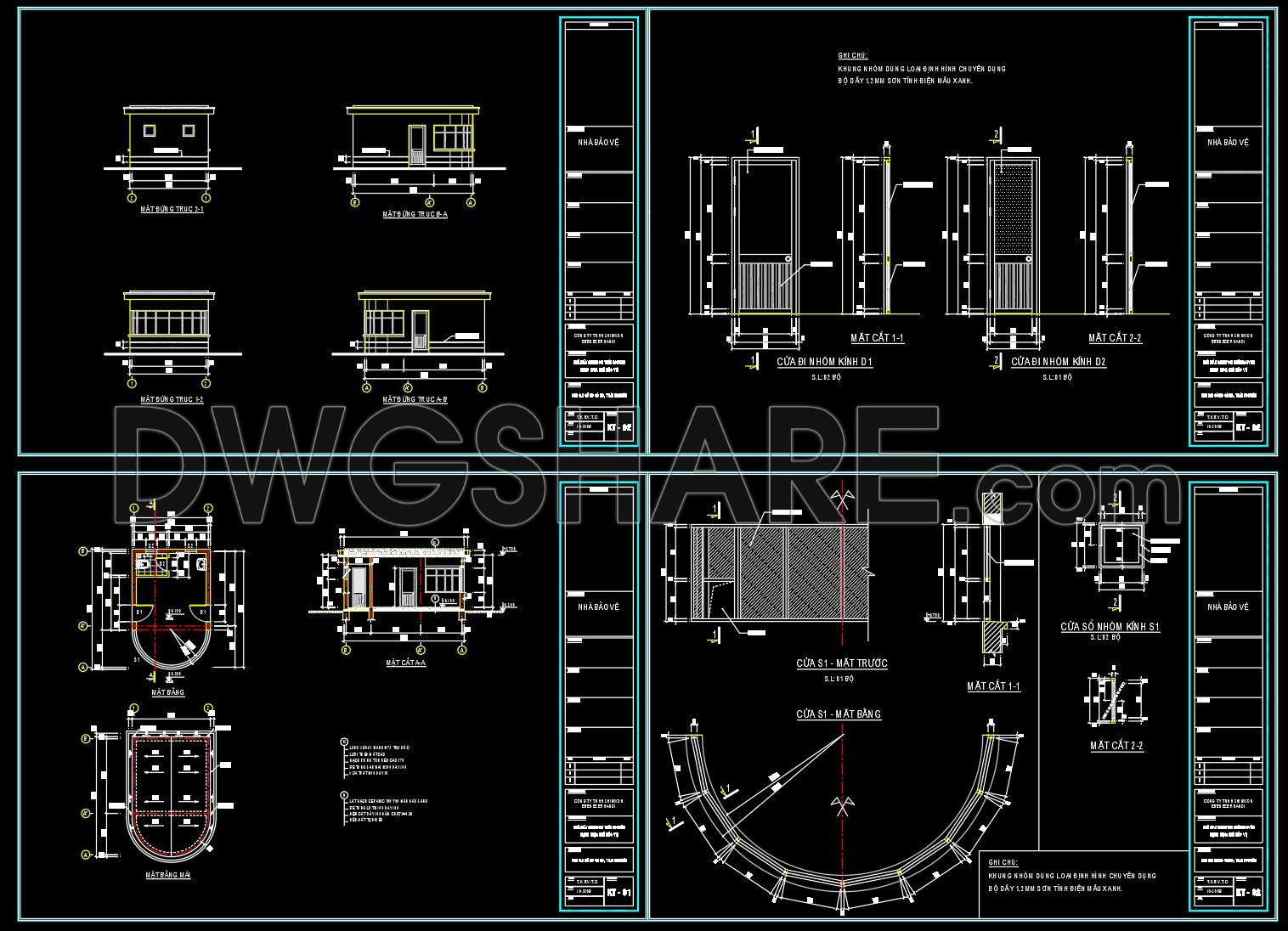
Starting with the architectural floor plans, they provide a clear view of the overall layout. Key elements seen in these drawings include precise dimensions, grid lines, and level markers. These are pivotal for architects during the initial stages of design development, ensuring that all aspects of spatial planning are accurately captured. Interior designers also benefit from these plans as they offer a foundational layout from which interior details can be elaborated.
Next, the elevations and sections reveal the vertical design components and spatial relationships. These drawings are indispensable for visualizing the exterior appearance and internal spatial arrangements. They serve as critical tools for construction teams to ensure adherence to the intended aesthetic and functional designs during building processes.
The inclusion of construction detail drawings further enhances this set by providing intricate details such as joint configurations, material specifications, and connection methodologies. These drawings are crucial for construction teams, offering a precise guide to material selection and assembly processes, reducing the possibility of errors and facilitating cost optimization.
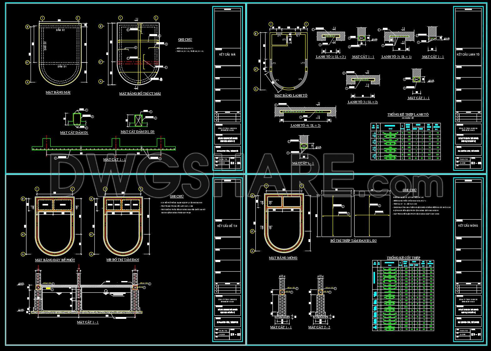
The presence of structural drawings highlights the structural integrity vital to any guard house. These include reinforcements, foundation details, and load-bearing specifications, ensuring the structure can withstand required loads and environmental conditions. Structural engineers rely on these drawings for validation and modification, enhancing safety and durability.
The drawings are meticulously created to ensure high technical accuracy. They are easily modifiable and reusable in AutoCAD, allowing for straightforward adaptations during project revisions. Moreover, these CAD files support improved coordination between design and construction teams, minimizing errors and promoting efficient resource management.
Available for free, these CAD DWG files are suitable for use as a design reference, enabling professionals and students alike to study and research. They also serve as a base for further technical drawing development, providing a springboard for more advanced architectural endeavors.
I also recommend downloading other Cad Details CAD drawings for your project reference.
- File format: .DWG
- Size: 1 MB
- Source: DWGshare
- AutoCAD platform 2018 and later versions. For downloading files there is no need to go through the registration process
Advertisements