

157. MEP Plumbing CAD Drawings for Residential Building
Advertisements
157. MEP Plumbing CAD Drawings for Residential Building
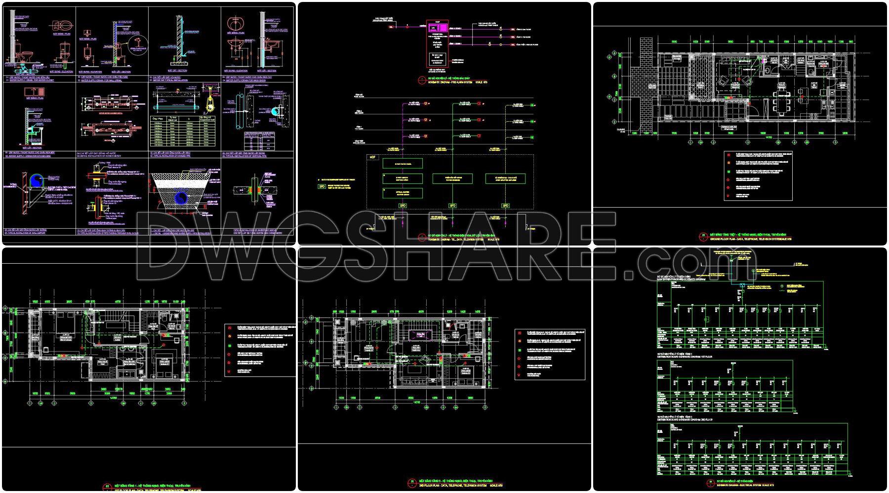
The MEP Plumbing CAD Drawings for Residential Building present a comprehensive view essential for the design and execution stages of a residential project. These CAD drawings are meticulously crafted to provide a clear understanding of the mechanical, electrical, and plumbing systems, highlighting how these components integrate cohesively to ensure efficient operation within the residential space.
Beginning with the functional floor plan layout, these drawings incorporate intricate details such as grid lines, dimensions, and level markers that are crucial for spatial planning and coordination. The floor plans give a clear spatial orientation, helping architects and construction teams visualize the placement of various systems relative to architectural elements.
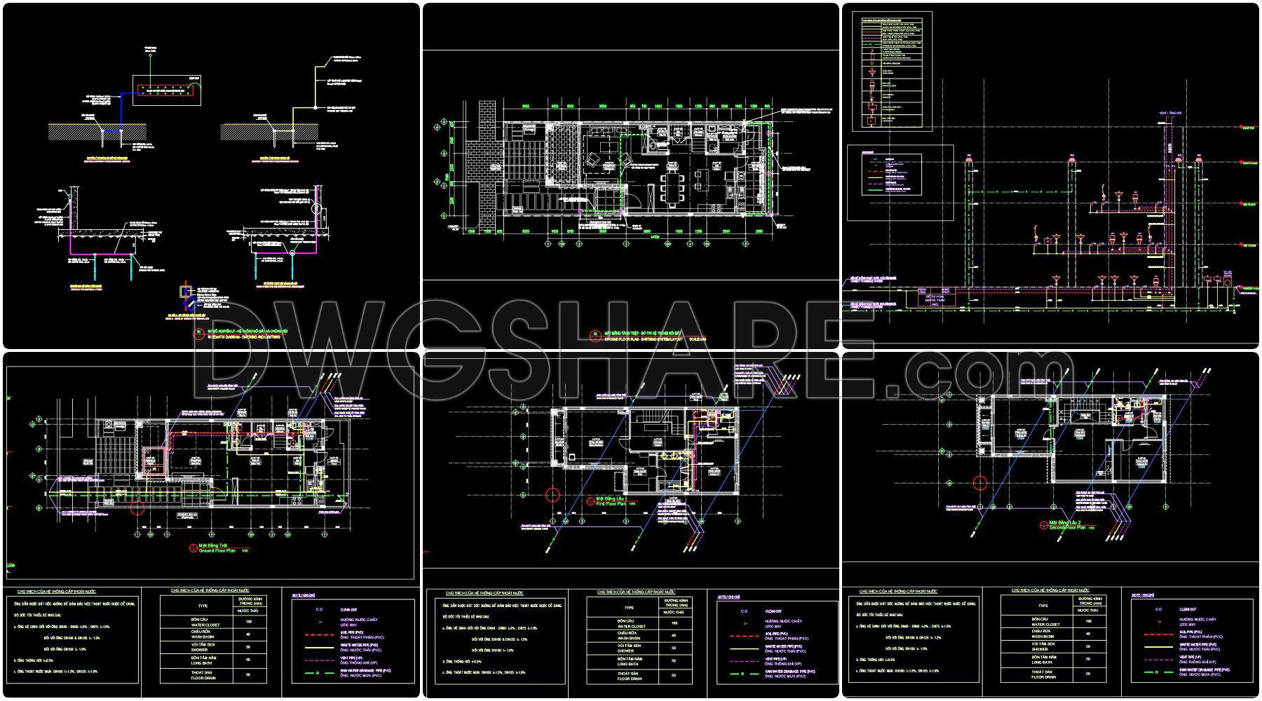
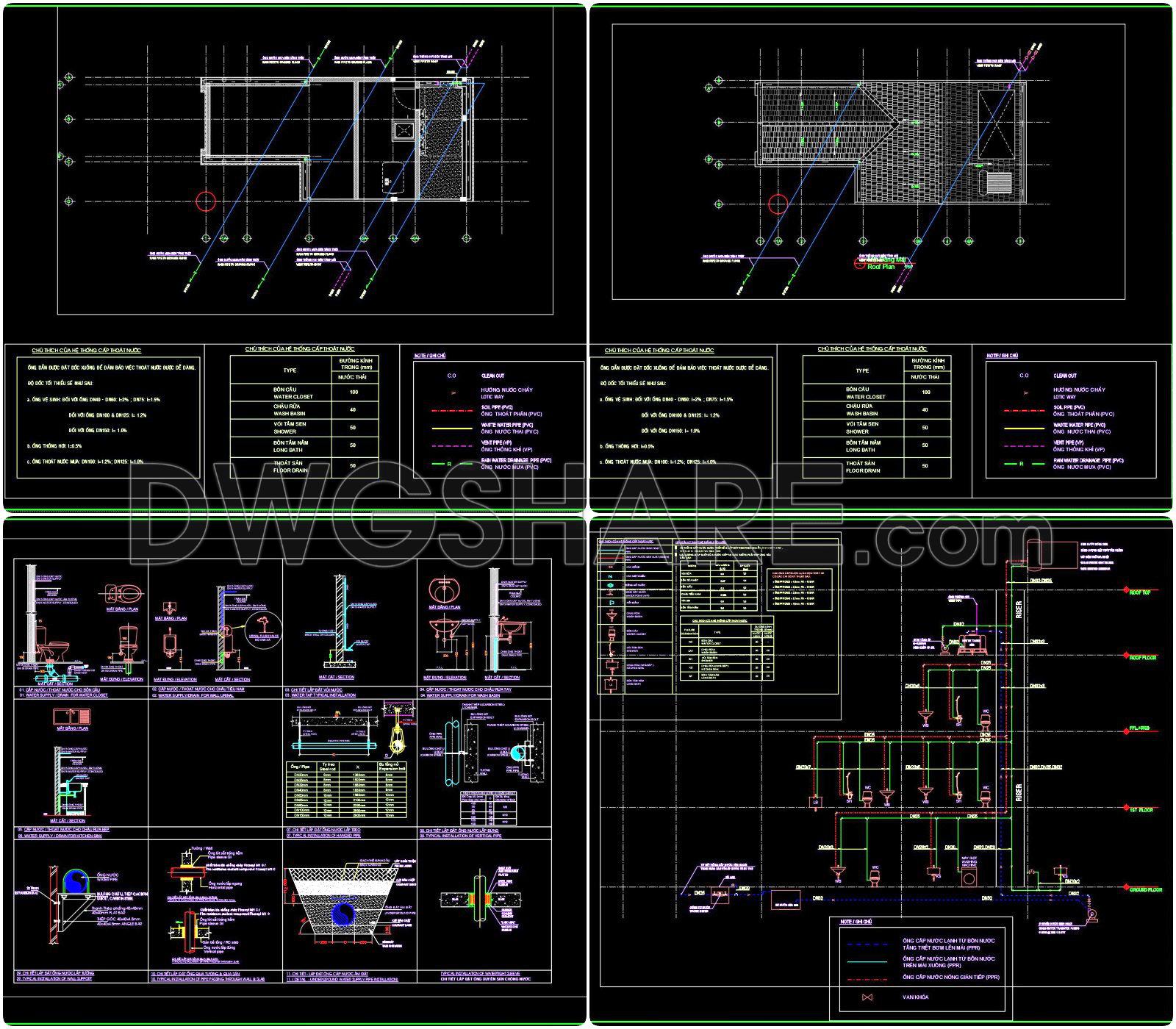
In addition to the floor plan, the CAD files include detailed plumbing sections and elevations. These are indispensable in illustrating the vertical relationships and interactions of plumbing elements across different building levels. The inclusion of sections allows designers to dissect the space, offering insight into pipe routing, fixture placements, and overall system vertical integration. The elevations provide a side-view, enhancing comprehension of how systems project beyond ground level.
Moreover, the construction detail drawings featured in these files deliver precision and clarity. These drawings are essential for the construction phase, as they highlight specific installation requirements, material specifications, and connection details. By providing this level of detail, they serve as a reliable reference to ensure installations are performed accurately, minimizing errors and optimizing costs.
Grid lines and level markers are highlighted throughout the drawings, ensuring that every component is aligned and positioned correctly. This technical precision is vital for maintaining structural integrity and ensuring that all services harmonize with architectural plans.
For architects, these CAD drawings are invaluable during the design development phase, offering an authoritative reference that aids in refining and adjusting designs with respect to functional and technical requirements. For interior designers, they present necessary technical details that inform fixture and fitting selections, ensuring these choices work in tandem with the building’s MEP layout. Construction teams employ these drawings extensively for on-site implementation, ensuring systems are built according to design specifications.
The practical value of these CAD drawings cannot be overstated. With their high technical accuracy and capacity for easy modification, they facilitate improved coordination between design and construction teams, reducing potential errors and leading to cost-effective outcomes. They are shared freely, making them an excellent resource for design reference, technical study, or as a base for further development.
These CAD DWG files are a necessary asset for professionals aiming to enhance their knowledge and proficiency in residential building design and construction. By offering these insights, they advance not only individual projects but also broader architectural practices.
I also recommend downloading other Buildings CAD drawings for your project reference.
- File format: .DWG
- Size: 20 MB
- Source: DWGshare
- AutoCAD platform 2018 and later versions. For downloading files there is no need to go through the registration process
Advertisements