

170. MEP Electrical CAD Drawings – Lighting, Power, HVAC, LAN & Telecommunication Systems
Advertisements
170. MEP Electrical CAD Drawings – Lighting, Power, HVAC, LAN & Telecommunication Systems
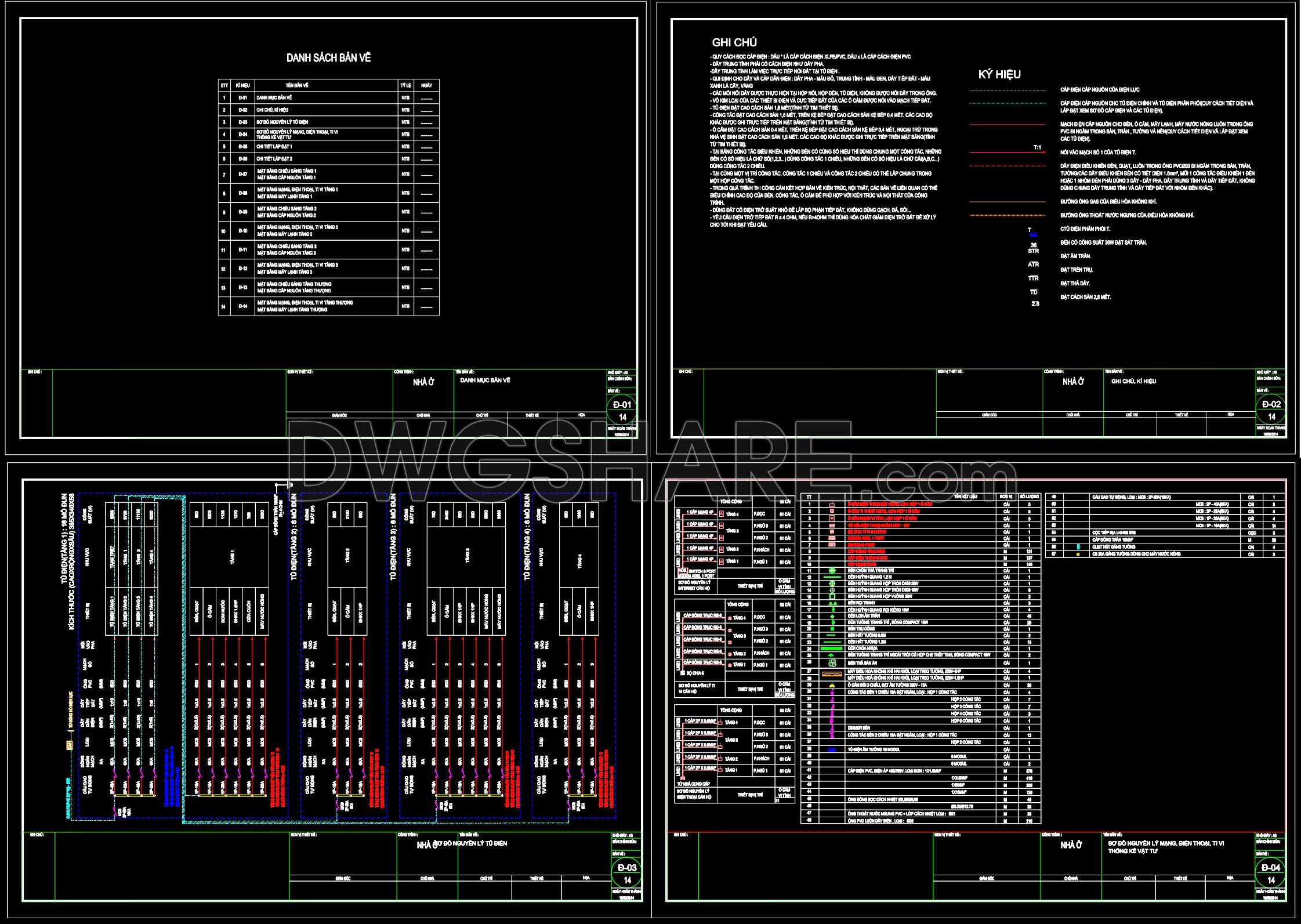
The collection of CAD drawings focusing on MEP Electrical CAD Drawings for Lighting, Power, HVAC, LAN, and Telecommunication Systems provides a comprehensive resource for architecture and construction professionals. These detailed drawings are essential for integrating electrical and mechanical systems into building designs, ensuring that complex infrastructural needs are met with precision and efficiency.
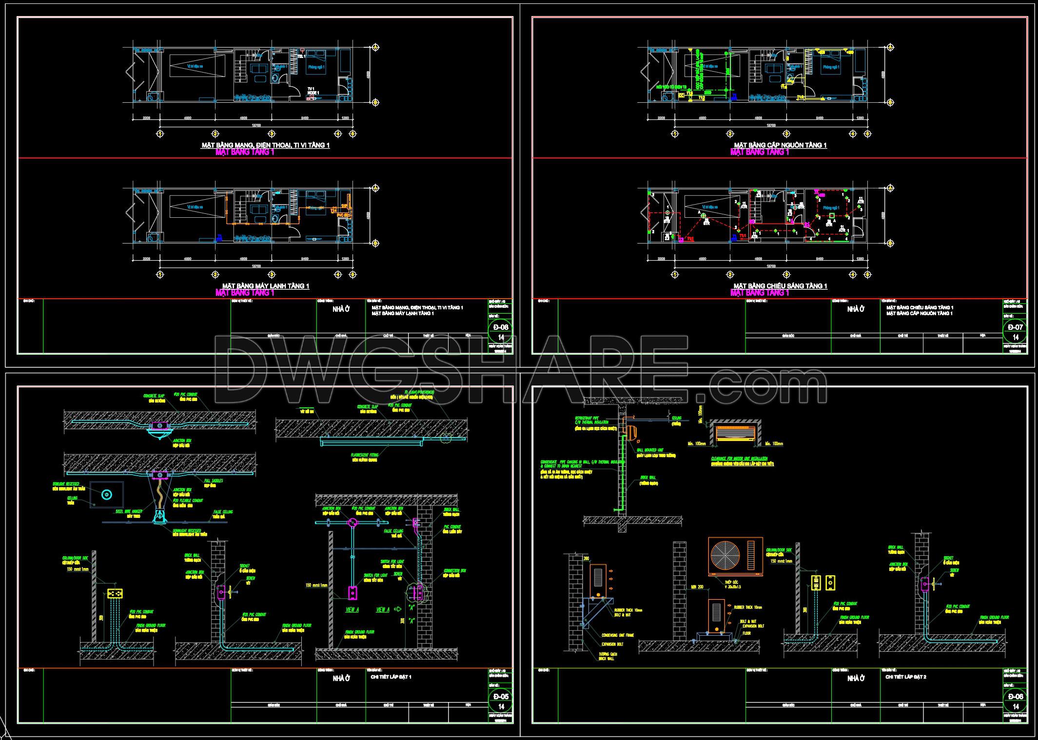
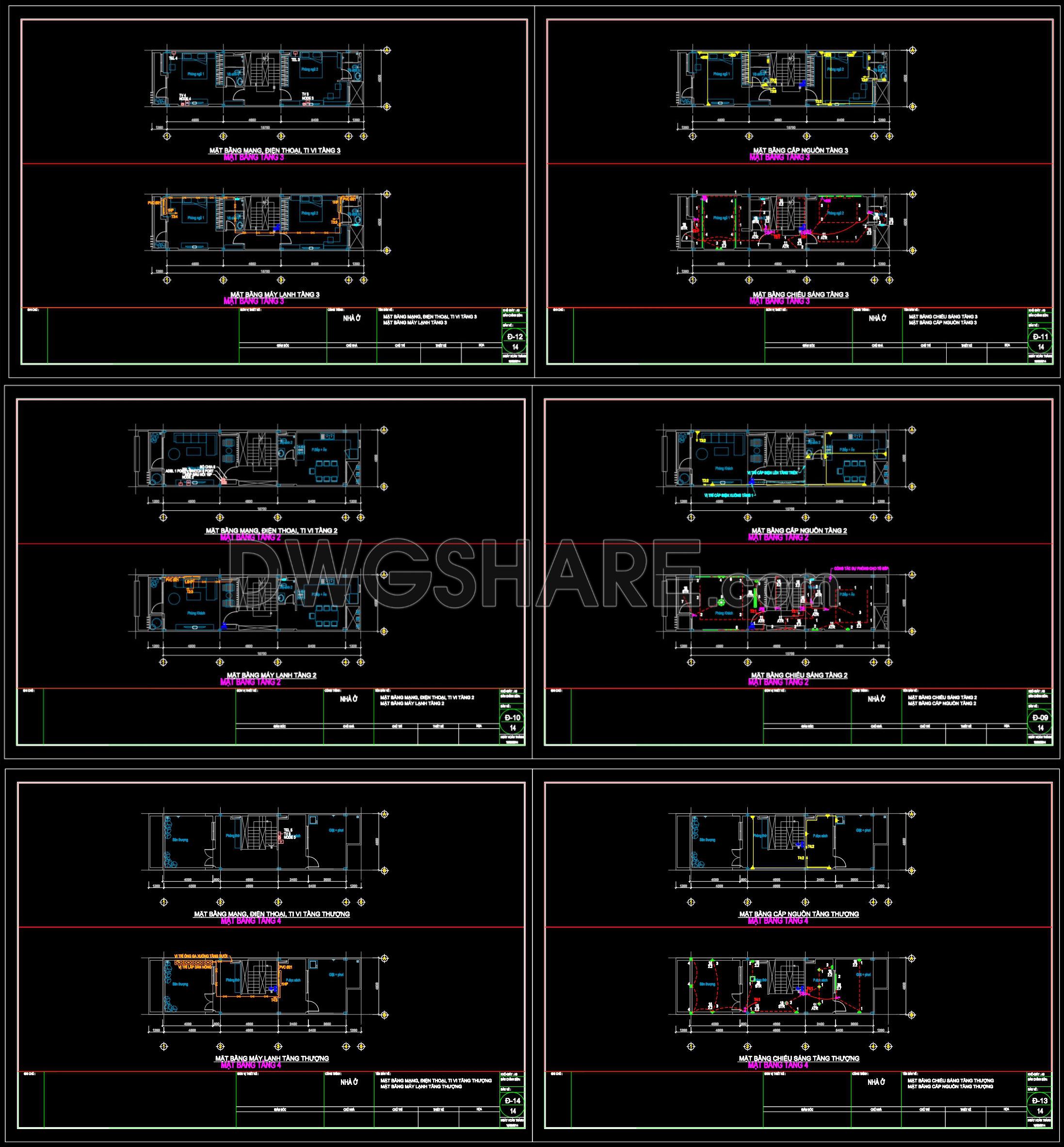
Beginning with the lighting and power layouts, these floor plans meticulously outline the positioning of fixtures, outlets, and circuits. Key components visible in the drawings include functional layouts with grid lines and dimensions, ensuring clarity and accuracy for implementation. Such precision assists architects in refining design elements during development phases and provides a clear guide for construction teams tasked with installation. Notably, every floor includes detailed wiring plans that are easily modifiable within AutoCAD, enhancing adaptivity for any design changes or project-specific requirements.
In the realm of HVAC systems, these CAD drawings offer a detailed look at air conditioning and ventilation setups. Detailed sections and elevation views highlight the intricate placement of ducts and vents, crucial for maintaining environmental control within the built spaces. With dimensions and level markers clearly presented, contractors can efficiently coordinate these systems with the overarching architectural framework, reducing potential errors and facilitating smooth construction workflows.
LAN and telecommunication frameworks are thoroughly documented, highlighting the integration of technology within modern infrastructure. These drawings provide essential layouts for data cabling and telecommunication devices, expertly demonstrating how these systems align with broader project designs. This information is invaluable for ensuring that connectivity needs are seamlessly incorporated from the early stages of construction planning.
Furthermore, the detailed system installation details are crucial for interior designers and construction teams. The technical accuracy of these CAD drawings ensures that every element, from minor fixtures to major system components, aligns perfectly during the build process. Builders can rely on these well-organized documents to minimize construction errors, optimize costs, and improve coordination between teams.
These CAD DWG files are offered free of charge for design reference, study, and research. They’re an ideal foundation for developing technical drawings, ensuring that projects remain on track and within budget. With these robust and actionable blueprints, professionals can lead projects from conception through execution with confidence.
I also recommend downloading other Mechanical, Electrical CAD drawings for your project reference.
- File format: .DWG
- Size: 1 MB
- Source: DWGshare
- AutoCAD platform 2018 and later versions. For downloading files there is no need to go through the registration process
Advertisements