

235. Steel Fence & Gate CAD Drawing – Plan, Elevation & Sections
Advertisements
235. Steel Fence & Gate CAD Drawing – Plan, Elevation & Sections
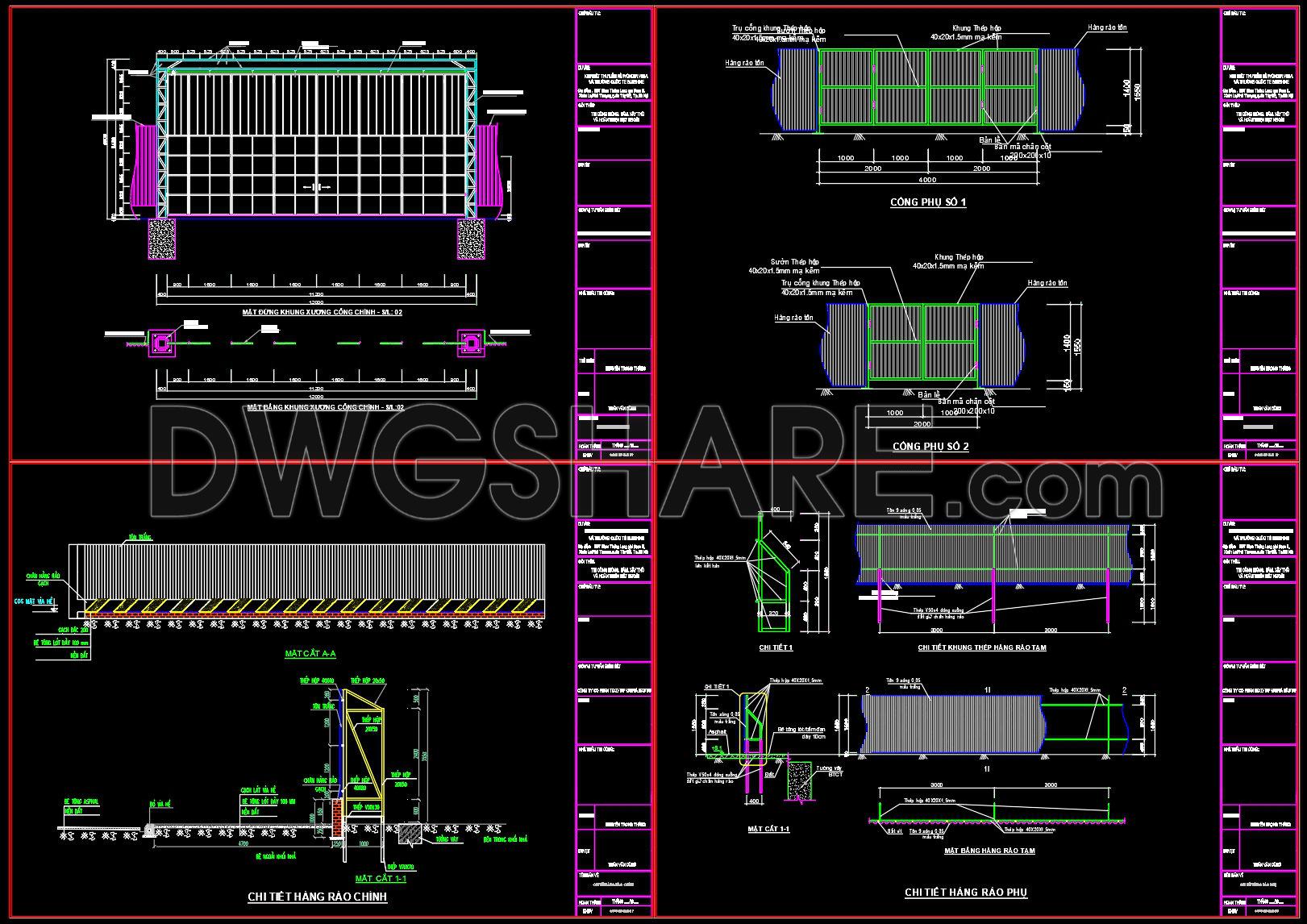
The Steel Fence & Gate CAD Drawing includes detailed plan, elevation, and section views integral to architectural and construction documentation. This comprehensive CAD drawing offers a clear plan layout of the fence and gate system, specifying dimensions, scale, and materials in technical precision. Beginning with the plan view, designers are provided with a spatial overview that includes critical measurements, ensuring that the installation aligns perfectly with the project requirements.
In the elevation views, the drawings deliver a vertical perspective, showcasing the height and structural design of both the fence and gate. This is crucial for visualizing the final appearance and ensuring compliance with aesthetic and regulatory standards. The elevation reveals the arrangement of panels and support structures, offering insights into the material interplay and geometric patterns that define the overall look.
The section drawings delve into the depth of construction details, highlighting how each component of the structure fits together. Sections are vital in understanding the layering and connections within the design, including the interface between the ground and the base of the fence or gate. These drawings often illustrate joint details and reinforcement features, essential for both architects and construction teams to refine technical specifications and construction methods.
The Steel Fence & Gate CAD Drawing is indispensable during design development and execution phases. Architects leverage these drawings to ensure their designs are accurately translated into the built environment. Interior designers use such details to harmonize outdoor elements with interior aesthetics, while construction teams rely on the drawings for precise fabrication and assembly instructions. The high technical accuracy of these CAD files facilitates improved coordination between design and construction teams, reducing errors and ultimately optimizing costs.
These CAD DWG files are shared freely, serving as an excellent resource for design reference, academic study, or as a foundational base for further technical drawing development. Their easy modification in AutoCAD allows users to adapt and customize designs as needed, enhancing versatility and efficiency in various projects.
I also recommend downloading other Cad Details CAD drawings for your project reference.
- File format: .DWG
- Size: 248 KB
- Source: DWGshare
- AutoCAD platform 2018 and later versions. For downloading files there is no need to go through the registration process
Advertisements