
548. Single-Storey Attached House CAD Drawing DWG – Floor Plans, Roof Plans, Elevations and Building Sections
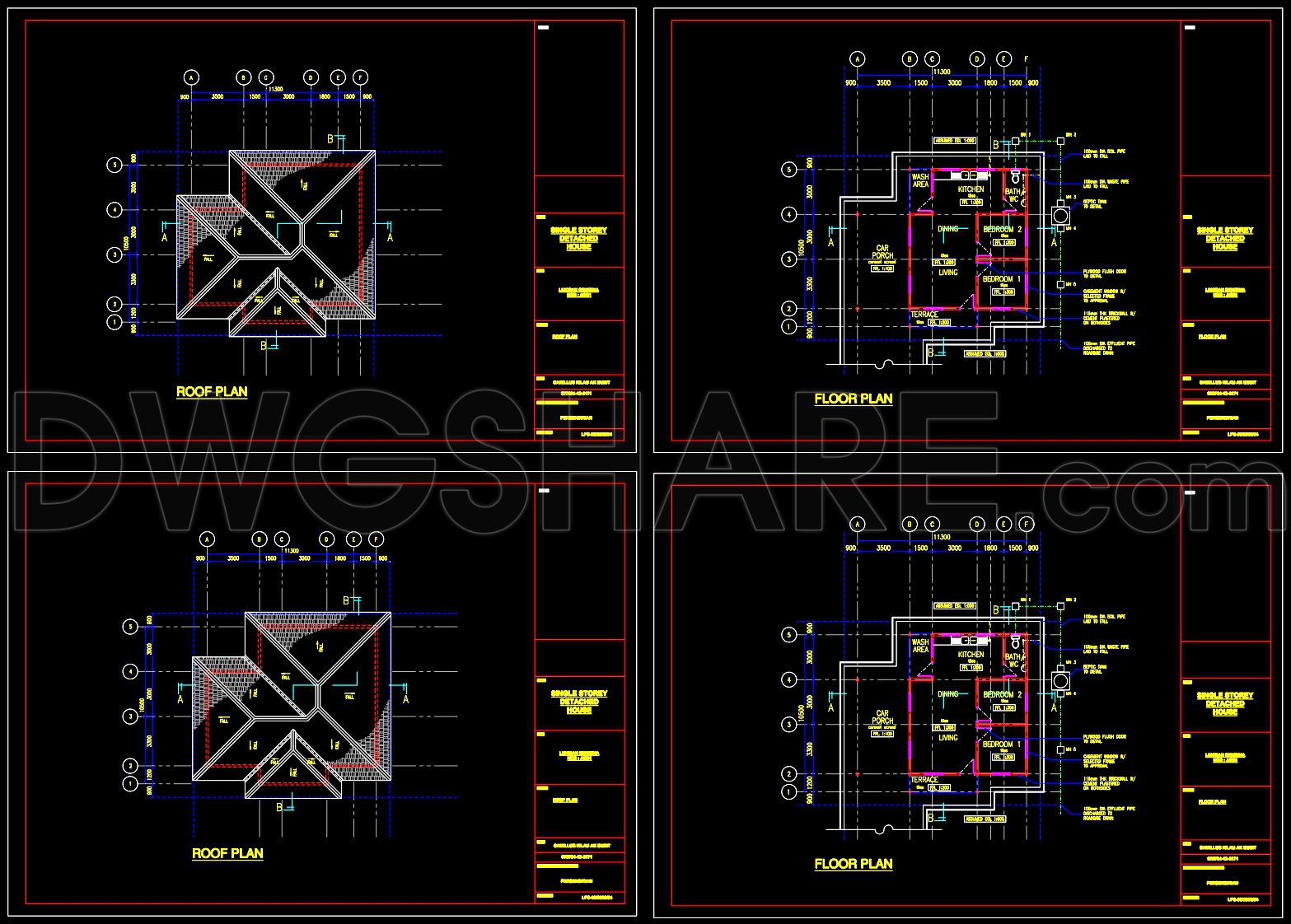
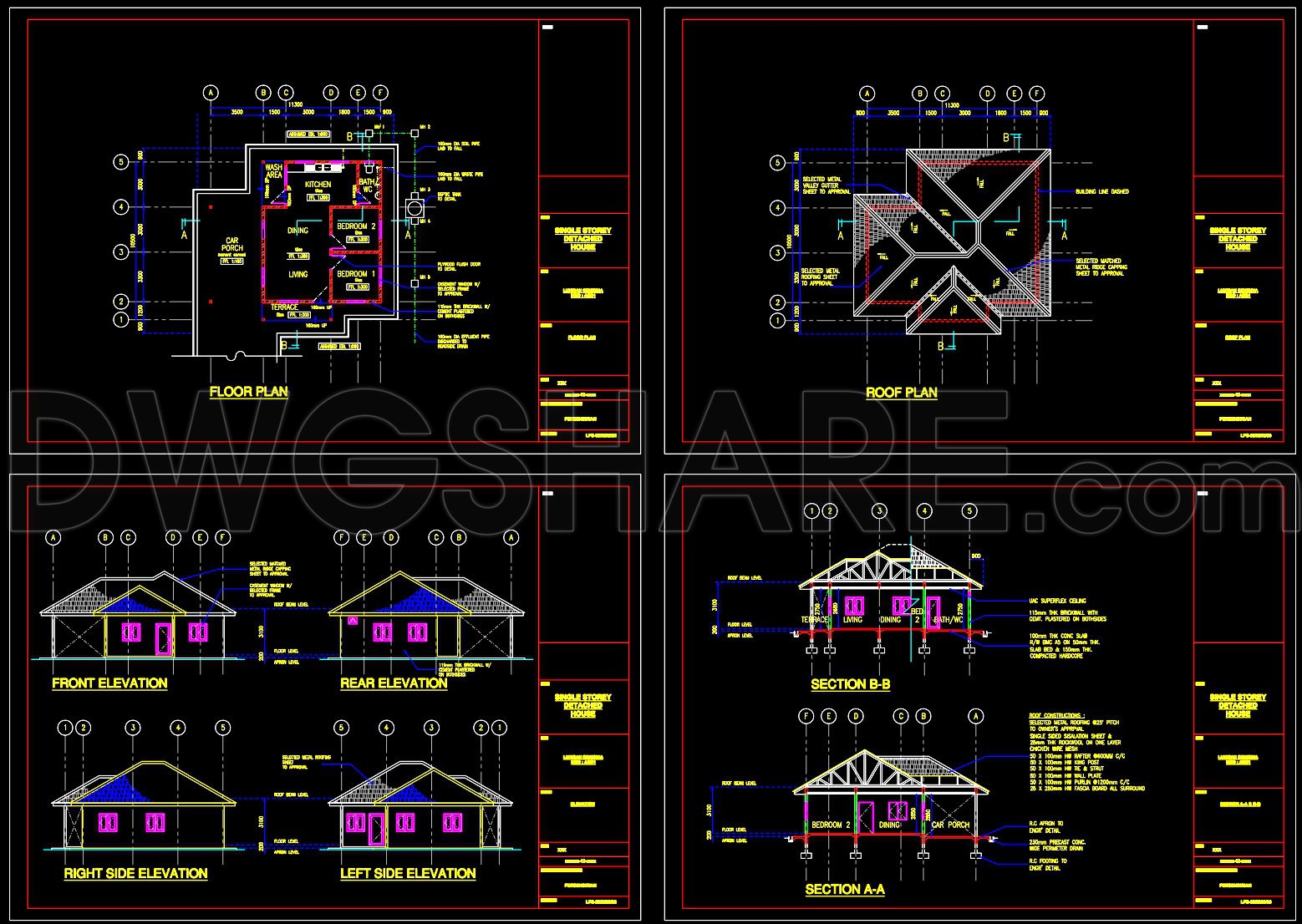
The single-storey attached house CAD drawing DWG offers comprehensive insights into architectural design through its meticulously detailed plans and elevations. The architectural floor plans serve as the core of these drawings, presenting a well-thought-out functional layout that includes key components such as the living room, kitchen, bedrooms, and essential service areas. Each space is clearly defined and marked with dimensions and grid lines, ensuring precise measurements that facilitate design accuracy and ease of construction.
Adjacent to the floor plans are the roof plans, illustrating the structural design and slope details necessary for effective water drainage and aesthetic appeal. The roof plans, marked with elevations and section lines, provide a crucial understanding of the roof’s structure, aiding architects and engineers in developing efficient roofing solutions that complement the overall design.
The elevations and building sections reveal the vertical dimensions and exterior elements of the structure. These drawings highlight crucial components such as facade treatments, window and door placements, and material specifications. The elevations, complemented by sectional views, allow architects to visualize the vertical interactions of spaces and materials, making it easier to communicate design intentions to clients and contractors.
Moreover, these CAD drawings are essential for interior designers, offering a foundational reference for technical details that ensure the harmonious integration of interior elements with the overall architecture. The detailed sections enable construction teams to accurately interpret the drawings for on-site execution, minimizing errors and enhancing coordination.
One of the standout features of these CAD drawings is their high technical accuracy and ease of modification in AutoCAD. This flexibility is invaluable for architects and engineers alike, enabling quick adjustments and adaptations as project requirements evolve. The DWG files promote enhanced coordination between design and construction teams, thereby optimizing costs and reducing potential errors during the construction process.
These drawings are shared freely, making them an excellent resource for design reference, academic study, and research. They also serve as an ideal base for further technical drawing development, allowing for reusability and customization based on specific project needs.
In conclusion, the single-storey attached house CAD drawing DWG is a versatile and valuable tool, offering significant advantages in architectural design and construction through its detailed plans, sections, and elevations.
I also recommend downloading other Cad Details CAD drawings for your project reference.
- File format: .DWG
- Size: 1 MB
- Source: DWGshare
- AutoCAD platform 2018 and later versions. For downloading files there is no need to go through the registration process
If you find our work useful, your support would mean a lot and help us grow even better.DONATE
Related posts
470. Download CAD Design Drawings for a 3-Story House with Dimensions 4m x 20m
Structural Drawings Of 2-Story House A Complete Project 10.5x12m For Download
145.M&E drawings Of 3-Story House A Complete Project 16.7×12.3m For Download
903. Download Architectural CAD Plans for a 3-Storey House (4,5m × 13,7m)
Entrance Layout Plan and Electric Details AutoCAD File Free Download
393. Download CAD Design Drawings for a 3-Story House with Dimensions 14m x 20m
Autocad Drawing Of 5-Story Classic Villa 9.6mx13.9m For Download
340. CAD design drawings for a 3-story townhouse with dimensions of 3.7m x 14m
434. Download Cad Design Drawings For A 3-story House With Dimensions 5m x 13.7m