

853. Complete Aluminum Glass Facade System CAD Detail in AutoCAD
Advertisements
853. Complete Aluminum Glass Facade System CAD Detail in AutoCAD
The complete aluminum glass facade system CAD detail serves as a comprehensive blueprint for architects, interior designers, and construction professionals. The drawings showcase meticulous architectural detail, emphasizing a complete system designed for modern facade applications. These detail drawings reveal the precision required in constructing efficient and aesthetically pleasing building exteriors.
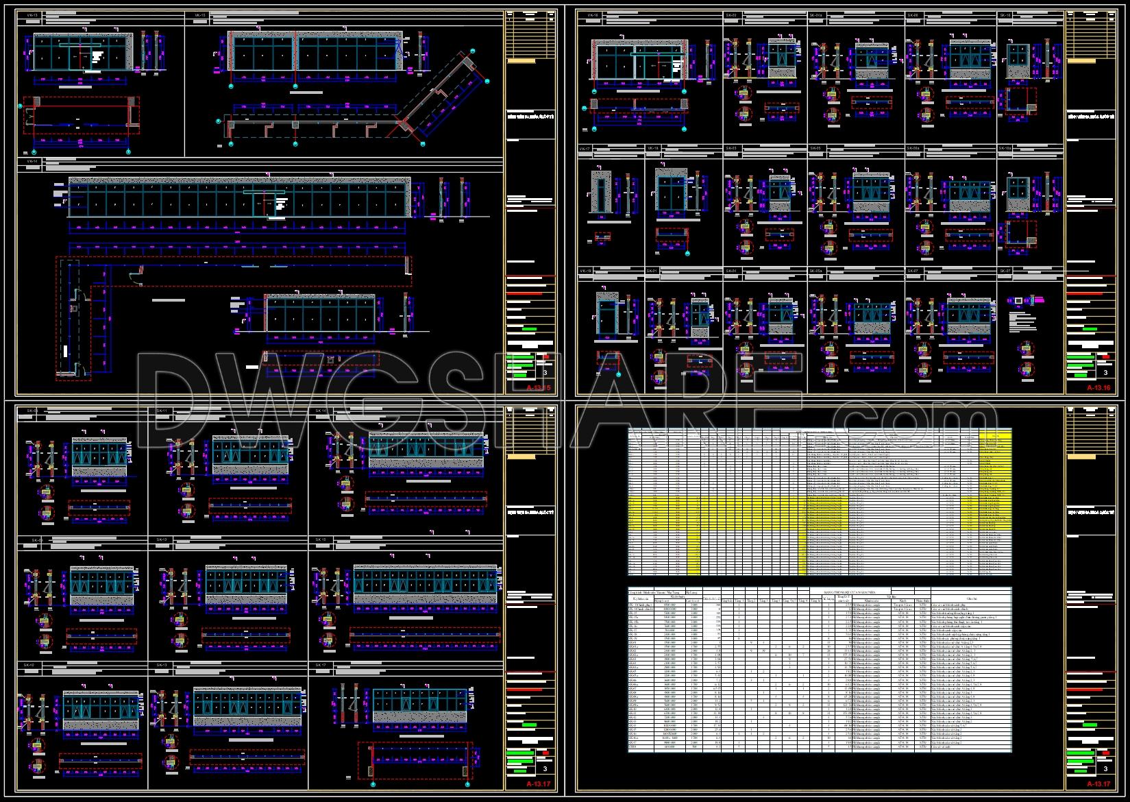
The set contains an array of components designed to ensure structural integrity and visual appeal. Key elements include section views that illustrate the cross-sectional intricacies of the facade system. These sections highlight various components like glass panels, aluminum framing, and connection joints, which are essential for robustness against environmental elements.
Additionally, the elevations provide a detailed front view of the facade, with precise dimensions and alignment guides. These elevation drawings are critical for aligning the glass panels and ensuring symmetry across the facade. The presence of grid lines and level markers is evident, aiding in the accurate alignment and positioning of facade elements. These markers are indispensable for construction teams to maintain precision over the entire height and width of the building structure.
Moreover, the drawings illustrate construction details that examine specific assembly aspects such as joinery, weatherproofing, and thermal insulation. This level of detail is crucial during the design development phase, allowing architects to predict performance issues and address them proactively.
From a practical standpoint, these CAD drawings are pivotal in various stages of project execution. Architects rely on them during the design development phase to foresee and rectify potential obstacles. Interior designers utilize these detailed accounts when coordinating facade aesthetics with interior themes, ensuring seamless transitions between inside and out. For construction teams, these drawings serve as a reference point, ensuring all elements are installed accurately and efficiently, reducing the risk of costly errors and delays.
The technical accuracy of these CAD drawings is high, facilitating easy modifications and adaptations in AutoCAD, which enhances coordination between design and construction phases. This prefabrication transparency helps in error reduction and cost optimization, making it an invaluable asset for any construction project.
These CAD DWG files are available for free, proving beneficial for design reference, academic study, or as a foundational template for further technical development.
I also recommend downloading other Door CAD drawings for your project reference.
- File format: .DWG
- Size: 1 MB
- Source: DWGshare
- AutoCAD platform 2018 and later versions. For downloading files there is no need to go through the registration process
Advertisements