

155. CAD drawings detailing the design of water supply and drainage systems for a 3-story townhouse
Advertisements
155. CAD drawings detailing the design of water supply and drainage systems for a 3-story townhouse
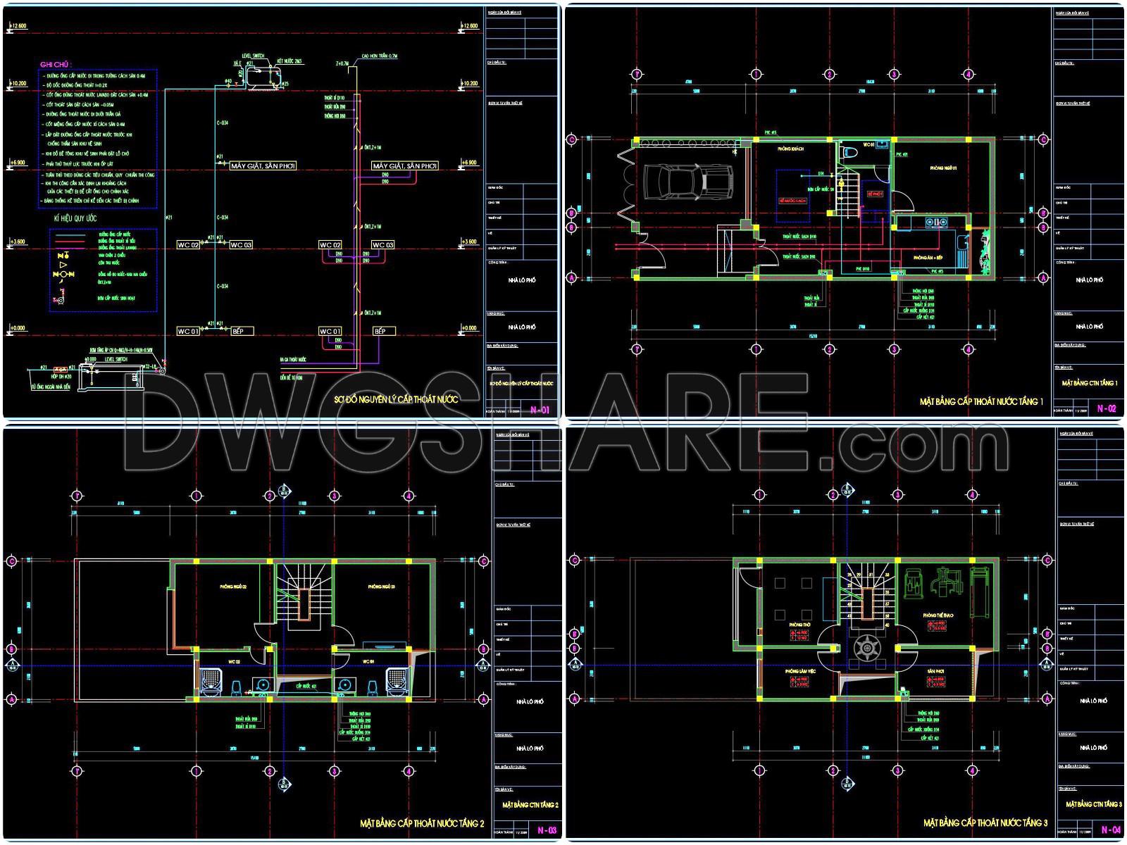
The CAD drawings detailing the design of water supply and drainage systems for a 3-story townhouse offer a comprehensive and technically precise set of resources necessary for successful architectural and construction planning. These detail drawings serve as an essential reference for ensuring the optimal functionality of the townhouse’s essential utilities.
Beginning with the functional floor plan layouts, the drawings present a clear depiction of each floor’s water supply and drainage configurations. These plans integrate essential elements such as grid lines and dimensions, accurately capturing the spatial relationships and technical specifications of the plumbing systems. This level of detail is particularly crucial for architects and planners during the design development phase, as it ensures that every pipe and fixture is accounted for within the building’s structure.
The inclusion of elevations and sections within the drawings provides an additional layer of depth to the design documentation. These perspectives are vital for visualizing the vertical arrangements and connectivity of the water systems between floors. For construction teams, these views facilitate precise on-site implementation and verification, reducing potential errors and thereby optimizing cost and time efficiency.
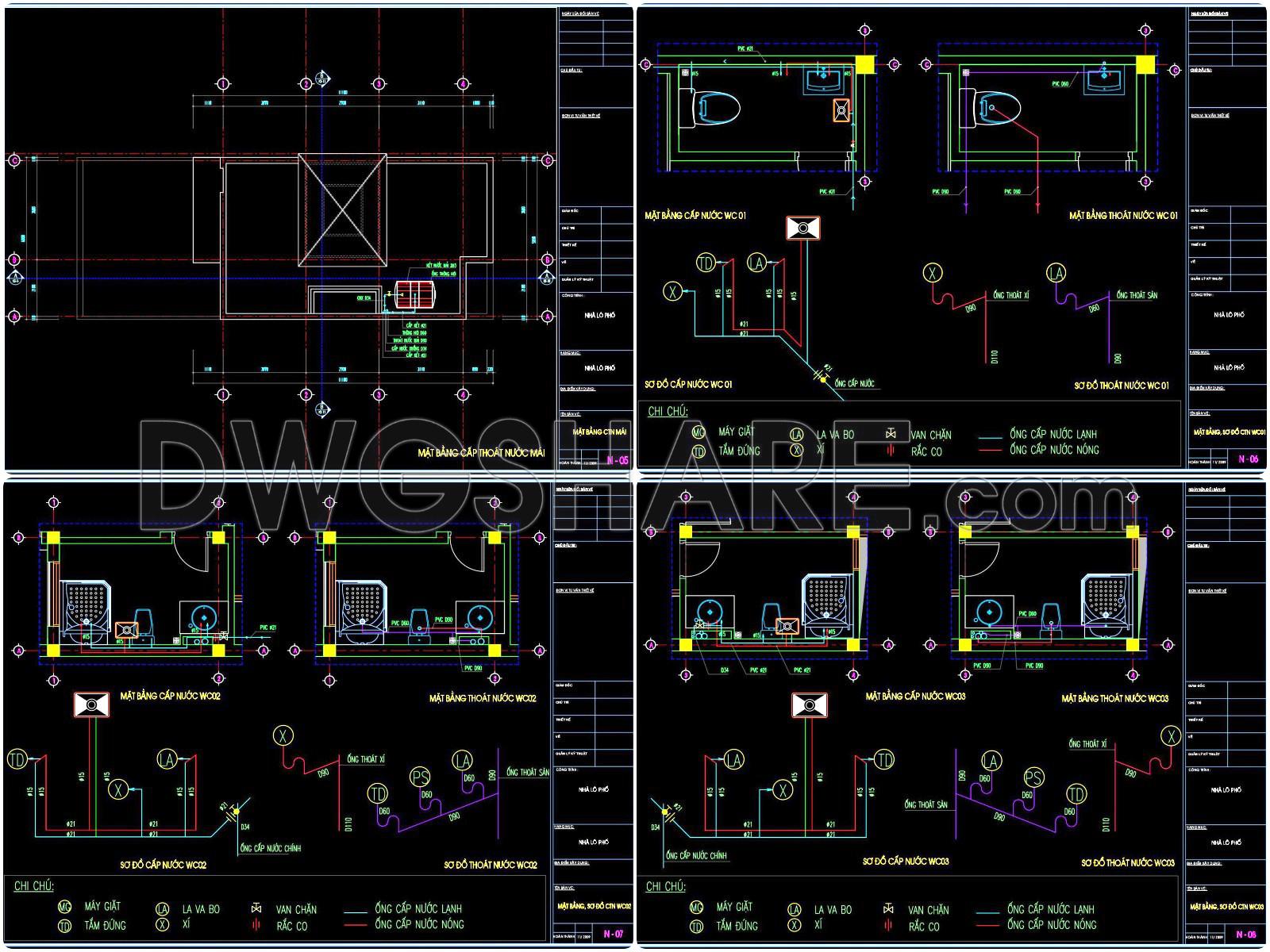
Each drawing is further enhanced by the incorporation of construction or plumbing detail drawings, showcasing specific components such as pipe joints, fixture installations, and valve placements. These detailed illustrations are indispensable for interior designers when preparing technical details or modifications. The accompanying grid lines, dimensions, and level markers enable easy interpretation and application, ensuring every aspect of the installations aligns perfectly.
Practically, these CAD drawings are designed for high technical accuracy. They allow for easy modification and reuse within AutoCAD, thereby improving coordination between design and construction professionals. This adaptability not only enhances precision but also significantly reduces errors, facilitating seamless integration and efficient project execution.
These highly valuable CAD DWG files are shared freely, providing an excellent base for design reference, study, and research. They can also be utilized as foundational templates for developing advanced technical drawings. The detailed representation within these files ensures a reduced likelihood of on-site discrepancies and promotes an overall deeper understanding of the water supply and drainage systems.
In conclusion, these detailed CAD drawings are indispensable tools within the architecture and urban planning fields. They support architects, interior designers, and construction teams by offering detailed insights into the water supply and drainage systems, thus contributing to more efficient and effective project delivery.
I also recommend downloading other Mechanical, Electrical CAD drawings for your project reference.
- File format: .DWG
- Size: 407 KB
- Source: DWGshare
- AutoCAD platform 2018 and later versions. For downloading files there is no need to go through the registration process
Advertisements