

169. House Plumbing CAD Drawings – Water Supply, Drainage and Sanitary System Plans
Advertisements
169. House Plumbing CAD Drawings – Water Supply, Drainage and Sanitary System Plans
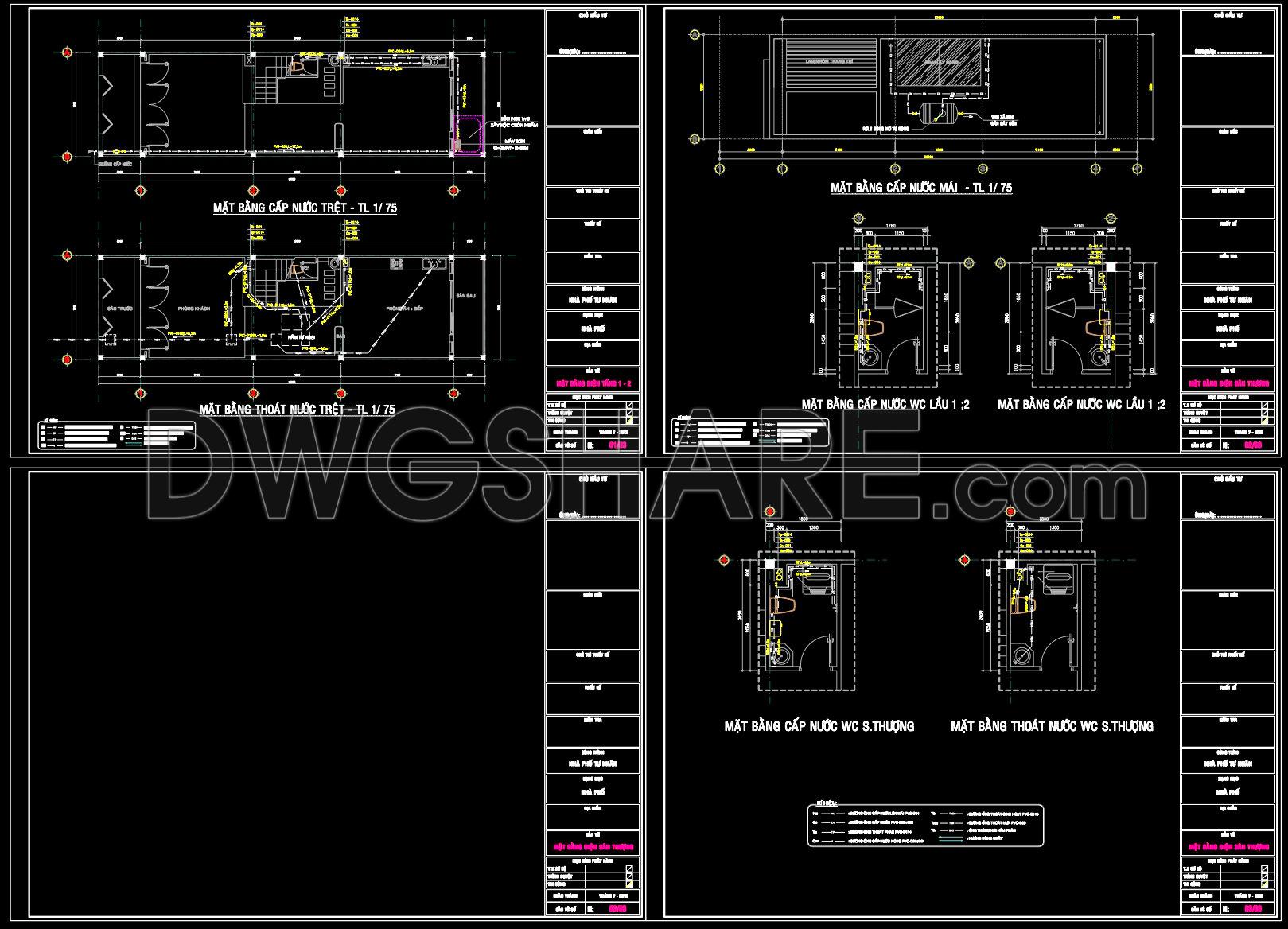
The House Plumbing CAD Drawings for water supply, drainage, and sanitary systems are integral to any architectural project. These detailed drawings form a foundation upon which efficient plumbing systems are designed, providing both functionality and sustainability in residential buildings. In this particular set of plans, each component is meticulously laid out to ensure optimal performance and ease of installation.
Beginning with the architectural floor plans, the drawings illustrate the layout of the water supply system. Key elements such as piping routes, fixture placements, and connection points are clearly marked. Each element is defined with technical precision, allowing architects and construction teams to visualize and execute the installation process effectively. The inclusion of grid lines, dimensions, and level markers provides a comprehensive blueprint that aids in the accurate translation of design into reality.
The elevations and sections provide a vertical perspective, highlighting the spatial arrangement of plumbing components across different levels of the building. This is essential for identifying potential challenges in system coordination, ensuring that plumbing elements do not clash with structural or aesthetic features of the building.
Next, the construction detail drawings offer in-depth views of specific components within the plumbing system. These details are crucial for contractors during the construction phase, providing precise measurements and specifications necessary for seamless assembly and installation.
The central role of these drawings is amplified by their high technical accuracy. CAD files such as these are easily modifiable, allowing for quick adjustments in response to design changes or site-specific requirements. This flexibility results in improved coordination between all parties involved—architects, interior designers, and construction teams—minimizing errors and operational costs. Architects find these files invaluable during design development, using them as a base for creating detailed technical documents. Interior designers can reference them to ensure compatibility between plumbing systems and design features, while construction teams rely on these drawings for precise guidance during the installation process.
These CAD DWG files, shared freely, are not only a practical tool for current design and construction projects but also serve as an educational resource. They are ideal for design reference, study, and technical drawing development, providing aspiring architects and engineers with a practical understanding of plumbing systems in architectural design.
I also recommend downloading other Mechanical, Electrical CAD drawings for your project reference.
- File format: .DWG
- Size: 186 KB
- Source: DWGshare
- AutoCAD platform 2018 and later versions. For downloading files there is no need to go through the registration process
Advertisements