

421. Download of Structural CAD Drawings for 10.8m x 17.1m Reinforced Concrete Townhouse
Advertisements
421. Download of Structural CAD Drawings for 10.8m x 17.1m Reinforced Concrete Townhouse
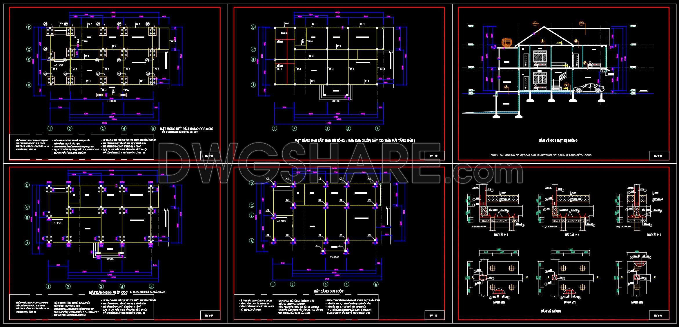
The Structural CAD Drawings for the 10.8m x 17.1m Reinforced Concrete Townhouse provide an essential resource for architects and construction professionals. These detailed structural drawings include comprehensive layouts and technical specifications crucial for successful project execution.
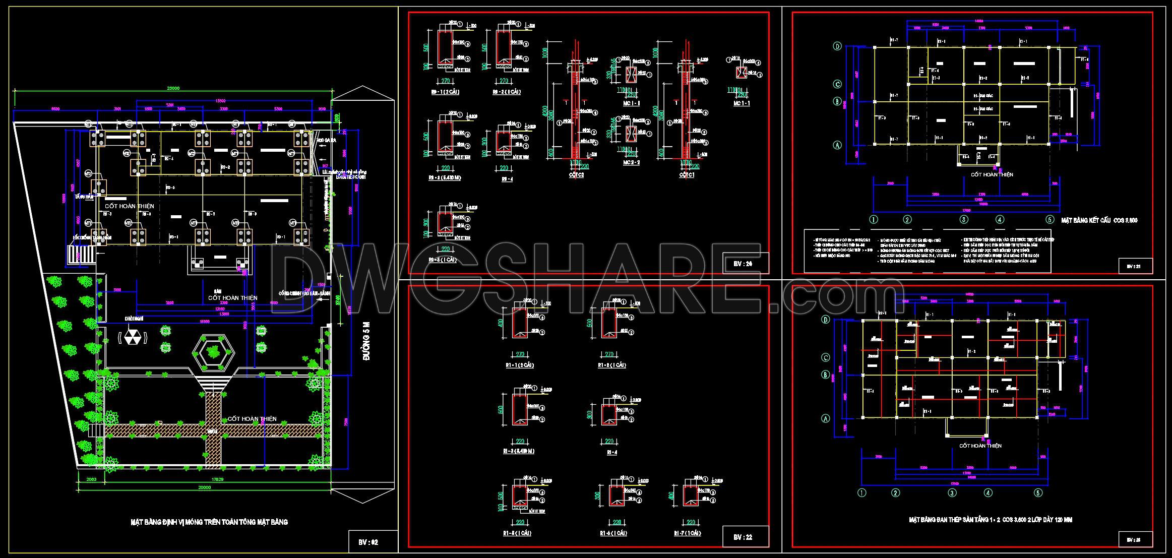
The drawings feature a precise functional floor plan layout that communicates the spatial arrangement and structure capability of the townhouse. It highlights the positioning of critical elements such as load-bearing walls and columns, which are fundamental in ensuring the building’s integrity. Accompanying the floor plan are elevations and sections that offer a side view of the structures, providing insight into height dimensions and cross-sectional details that are indispensable during the construction phase. These views are crucial for visualizing the spatial relationships and verifying the architectural design’s compliance with structural requirements.
Additionally, the construction detail drawings delve into the nitty-gritty of connection points and reinforcement techniques. These components are invaluable for engineers and builders aiming to understand the finer points of material assembly and the structural framework’s robustness. Grid lines, dimensions, and level markers are meticulously presented, facilitating precise measurement and alignment, which are critical during on-site construction processes to avert structural miscalculations.
These CAD drawings play a pivotal role in design documentation by providing architects the necessary information for design development. Interior designers can leverage these plans to craft layouts that align with the structural confines and allowances, ensuring both aesthetics and functionality are achieved. For construction teams, these drawings serve as a primary reference during building execution, providing a coordinated framework that guarantees the construction aligns precisely with the designed plans. This level of detailed coordination inevitably reduces errors and optimizes costs, minimizing the potential for costly alterations or design misinterpretations.
The practical value of these CAD drawings extends further due to their high technical accuracy and ease of modification within AutoCAD software. This flexibility is beneficial for making iterative design adjustments and reusing these plans across similar projects, which streamlines the design process and enhances workflow efficiency. The drawings are also shared freely for design reference, educational study, and to serve as a foundational base for developing new technical drawings, making them an excellent resource for both academic and professional settings.
By investing in these meticulously prepared CAD drawings, professionals ensure enhanced coordination between design and construction, fostering a seamless transition from conceptual design to actual building, while prioritizing cost-efficiency and error reduction.
I also recommend downloading other Structural CAD drawings for your project reference.
- File format: .DWG
- Size: 1 MB
- Source: DWGshare
- AutoCAD platform 2018 and later versions. For downloading files there is no need to go through the registration process
Advertisements