
Advertisements
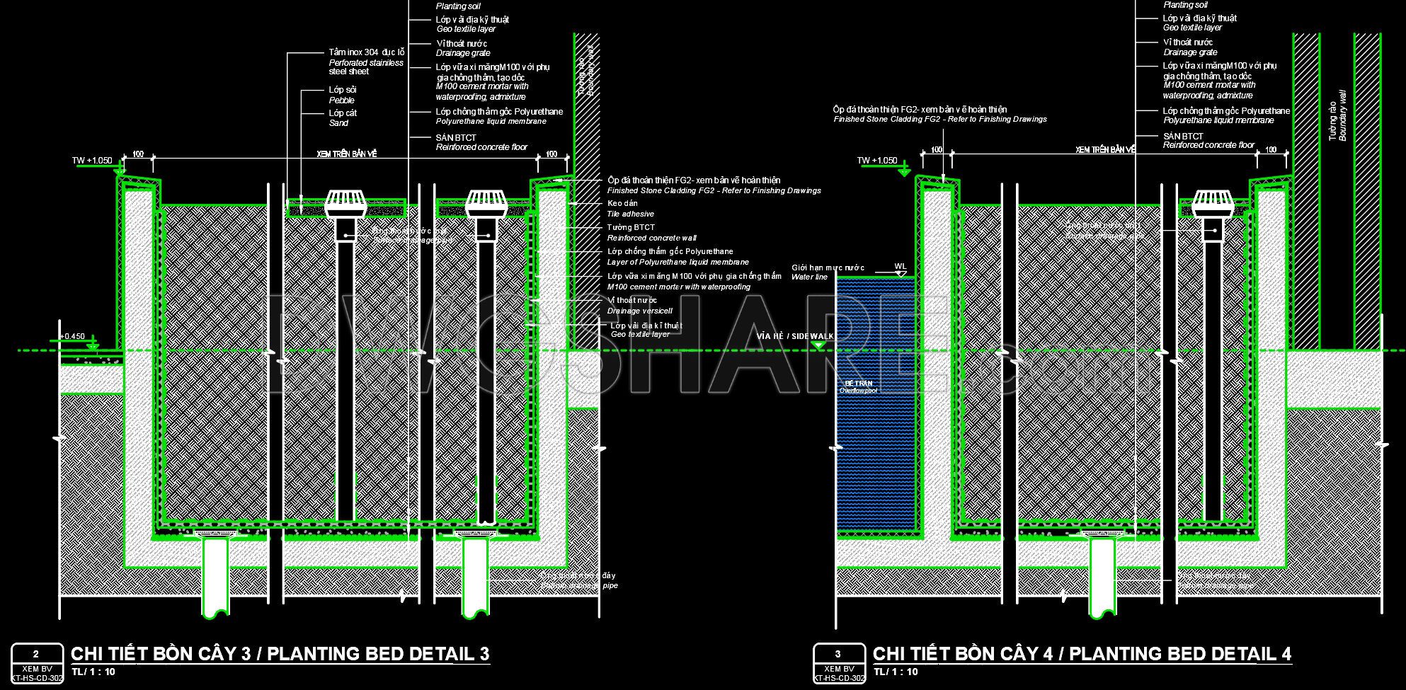

The drawing consists of three section views at varying levels of detail, describing the structure’s composition from a general overview to specific components.
Overview:
- Purpose: This drawing serves as a construction guide, clearly defining the material layers, dimensions, and installation methods for the underground pit.
- Main Structure: It features a reinforced concrete box set below ground or slab level. The structure includes pipe sleeves that penetrate the base slab.
Detailed Description of Each Section:
1. Section 1:
Advertisements
- This view displays the overall structure of a smaller box, which may be a different variant or part of a larger system.
- It shows the concrete walls and base.
- The interior is filled with a hatched material (representing soil media or a filter layer).
- Pipe sleeves are shown extending upwards from the base.
- Basic dimensions and surface finishing layers are annotated.
2. Section 2:
- This is the most detailed cross-section, clearly illustrating every construction layer.
- Concrete Walls and Base: These form the primary structural element.
- Waterproofing Layer: A waterproofing membrane is applied to the external face of the concrete wall to prevent water ingress from the surrounding soil.
- Protection Layer: Protection boards and/or drainage cells are placed outside the waterproofing membrane to protect it from damage during backfilling.
- Interior: The box is filled with a hatched material (e.g., soil, gravel, or engineered filter layers). Three large pipes run vertically from the base to the top.
- Top Finishing: The top edge of the box is meticulously detailed with coping, a drainage channel, and surface finishing materials (e.g., granite pavers).
- Drainage Pipes: PVC pipes penetrate the concrete base, likely for irrigation or drainage. The pipe penetrations are carefully sealed to maintain water tightness.
3. Section 3:
- This view focuses on the detail at the junction between the underground box and an adjacent wall or structure.
- It provides further clarification on the waterproofing and protection layers on the side abutting the wall.
- It also shows the composition of the adjoining wall (possibly a basement wall).
In summary, this is a professional and detailed technical drawing used in construction. It specifies the complete assembly of an underground concrete planter box or utility pit, with a strong emphasis on waterproofing solutions and finishing details.
430. Free Download Detailed CAD Drawing of a Concrete Planter Box
Additionally, you can browse and download more free CAD drawings of technical construction details here.
- File format: .DWG
- Size: 760 KB
- Source: Collect
- AutoCAD platform 2018 and later versions. For downloading files there is no need to go through the registration process
💡Remark: You’re welcome to contribute resources to DWGshare.com by sending us your PDF, DWG, or ZIP files here or via email at [email protected]. Thank you — we truly hope that each of your contributions will help build a stronger and more connected CAD community.
If you find our work useful, your support would mean a lot and help us grow even better.DONATE
If you find our work useful, your support would mean a lot and help us grow even better.DONATE
Related posts
252. Download detailed CAD drawings of the glass roof lighting details, and balcony details for a townhouse
269. Detailed architectural CAD drawings of the roof and garden landscaping of the townhouse
503. Free download of CAD drawings of European classical architectural details
820. Free Download Detailed CAD Drawings of Modern Interior Glass Door with Metal Frame
179. Free Download CAD Kitchen Design Drawings – Apartment Floor Plan and Elevations
44.Autocad stretchable dynamic block Free download
522. Free download of detailed architectural CAD drawings for facades, balconies, staircases in townhouses
506. Free Download of CAD drawings of European classical architectural details
335. Detailed architectural CAD drawings of the balcony, railing of the townhouse