

803. Concept Floor Plan Drawing for a 2-Storey House (511m2) – CAD Concept Layout
Advertisements
803. Concept Floor Plan Drawing for a 2-Storey House (511m2) – CAD Concept Layout
The concept floor plan drawing for a 2-storey house (511m2) provides a comprehensive layout of the architectural elements required for efficient design and construction coordination. These architectural floor plans serve as a critical foundation for architects and construction teams, offering an intricate overview of spatial arrangements and structural positioning.
The primary components within the CAD drawings include:
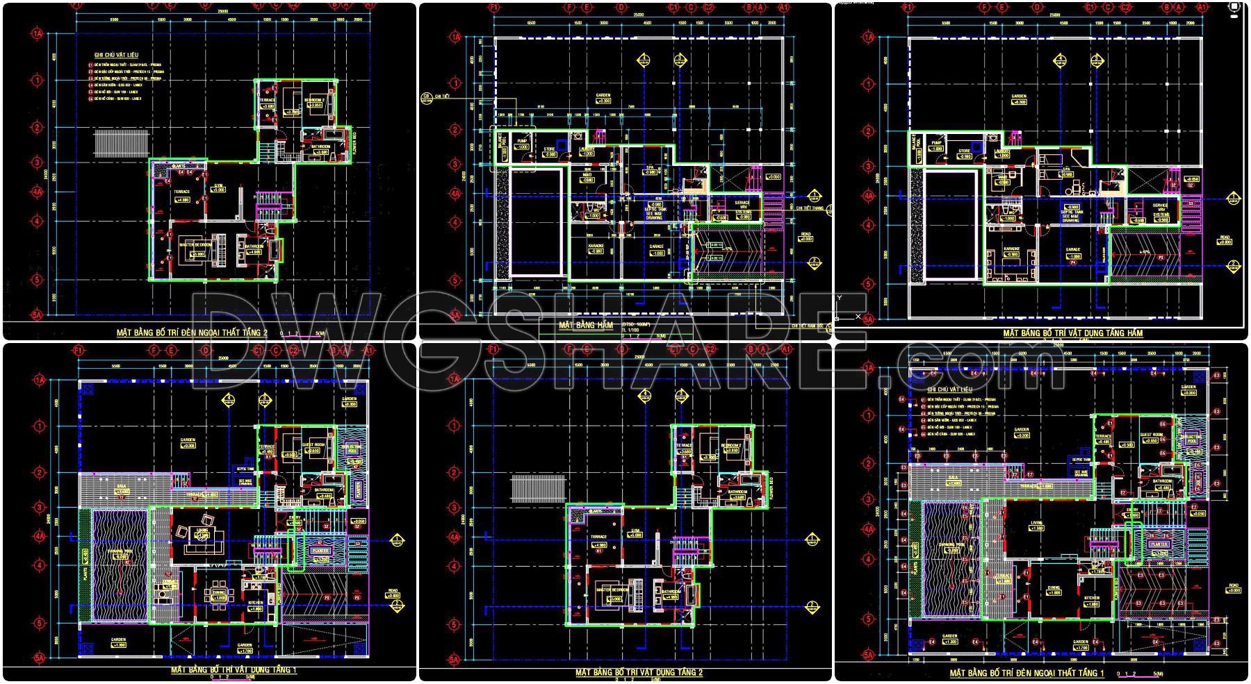
Functional floor plan layout: This outlines the spatial distribution across the two storeys, allowing architects to visualize the flow and connectivity between different spaces. Each room is meticulously labeled to assist in identifying specific functions and ensure that interior spaces meet design specifications.
Grid lines and dimensions: Essential for accurate project execution, the grid lines serve as a reference point during both design and construction stages, facilitating seamless coordination. Accompanied by precise dimensions, these elements ensure that every component fits perfectly within the intended design.
Elevations and sections: These provide detailed views of the house’s vertical dimensions and cross-sectional areas, offering clarity on heights and the structural interplay between different levels. This is particularly useful for interior designers preparing technical details and for construction teams visualizing the real-world implementation of design concepts.
These CAD drawings are invaluable tools due to their high technical accuracy and the ease with which they can be modified and reused in AutoCAD. This adaptability not only improves coordination between design and construction but also reduces errors and optimizes costs. Construction teams rely heavily on such precise documentation to minimize on-site adjustments, leading to more efficient resource allocation and time management.
Shared freely, the CAD DWG files are ideal for design reference, study, and research. They provide an excellent base for developing technical drawings, allowing professionals and students alike to explore and refine design strategies grounded in real-world architectural challenges.
In summary, this concept floor plan drawing effectively combines function and precision, ensuring that architects, interior designers, and construction teams can collaborate efficiently. By facilitating improved design development and on-site execution, these CAD drawings play a pivotal role in the successful realization of architectural projects.
I also recommend downloading other Store, Shop CAD drawings for your project reference.
- File format: .DWG
- Size: 1 MB
- Source: DWGshare
- AutoCAD platform 2018 and later versions. For downloading files there is no need to go through the registration process
Advertisements