

849. uPVC Glass Wall CAD Detail – Section & Construction Drawing
Advertisements
849. uPVC Glass Wall CAD Detail – Section & Construction Drawing
The uPVC Glass Wall CAD Detail offers an intricate look at the construction and section drawing of a contemporary glass wall system. As a detailed section drawing, this CAD file serves as an essential tool for architects and construction professionals focused on modern building designs that incorporate innovative materials like uPVC. The precision of these details in the drawing augments the understanding of how such a structure is assembled, facilitating both design development and construction processes.
This drawing includes several key features that are instrumental in its application. Among the components, you’ll find:
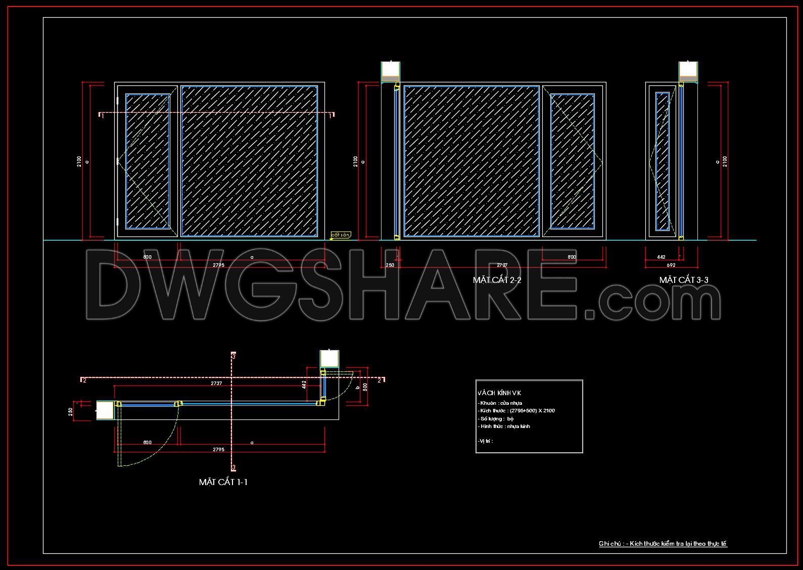
Elevation views showcasing the vertical elements of the glass wall, emphasizing the arrangement and size of the uPVC frames.
Section cuts that provide in-depth insights into the layers and construction techniques used to ensure both structural integrity and aesthetic appeal.
Dimensional annotations clearly indicate the scale and measurements necessary for accurate implementation in a real-world setting.
Grid lines and level markers that offer reference points for precise alignment and verification during construction.
The uPVC Glass Wall CAD Detail is of immense practical value. Architects use such drawings for the meticulous detailing process during design development, ensuring every aspect of the construction is well-planned. Meanwhile, interior designers leverage these technical details to integrate the glass wall seamlessly into the broader design context, harmonizing functional requirements with visual sensibilities.
Construction teams benefit from the precision of these drawings, using them to coordinate installation and mitigate potential errors. The high technical accuracy inherent in these CAD files allows for easy modification and adjustment, optimizing project costs and timelines. The adaptable nature of CAD drawings means they remain a pivotal reference throughout the project’s lifecycle, enhancing both design accuracy and construction efficiency.
Available for free usage, this CAD file is ideal for use as a design reference, as well as for educational purposes. Students and professionals alike can use it to study the intricacies of modern construction materials and methods, providing a foundational base for further technical drawing development. The ability to reuse and modify within AutoCAD enhances the accessibility and utility of these files, ensuring they remain a versatile tool in any architectural or construction toolkit.
I also recommend downloading other Cad Details CAD drawings for your project reference.
- File format: .DWG
- Size: 101 KB
- Source: DWGshare
- AutoCAD platform 2018 and later versions. For downloading files there is no need to go through the registration process
Advertisements