
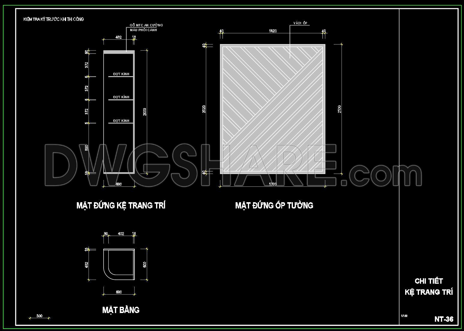
215. CAD Drawing of Decorative Shelf and MDF Wall Cladding Detail
The detailed CAD drawing of a decorative shelf and MDF wall cladding presents an intricate blueprint essential for architectural and construction practices. This drawing serves as a critical reference point for both design innovation and practical implementation in modern interior spaces. It includes precise elevation views, sections, and construction detail drawings, which are indispensable for architects, interior designers, and construction professionals.
The elevation view of the decorative shelf delineates its vertical layout, providing insights into its structural elegance and functional utility. The shelving design is clearly marked with dimensions such as height, width, and depth, allowing for meticulous planning during construction. Each measurement, consistently presented in millimeters, ensures high technical accuracy, facilitating seamless design verification and adaptation for various spatial configurations.
Adjacent to the shelf elevation is the MDF wall cladding detail, highlighting the intersection of aesthetic design with practical application. The drawing’s distinct patterning showcases how wall cladding can transform a plain surface into an engaging visual element. This detail is pivotal for interior designers as they focus on material selection and application techniques that enhance the ambiance and functionality of a room.
The plan and elevation drawings are further complemented by essential features like grid lines, dimensions, and level markers, which guide construction teams in maintaining alignment, proportional integrity, and the overall symmetry during installations. The incorporation of these details minimizes errors, optimizes construction costs, and fosters efficient project timelines.
From a practical standpoint, these CAD drawings afford a multitude of advantages. Architects employ them during the design development phase to ensure coherence between conceptual blueprints and technical realities. Interior designers utilize these plans for precision in aligning aesthetic goals with structural feasibility. Construction teams benefit from the clarity and reliability of these drawings, which aid in accurate on-site execution and necessary adjustments.
The high technical accuracy of these drawings, along with their compatibility with AutoCAD, allows for easy modification and reuse, ensuring they remain a valuable resource for future projects. This not only enhances coordination between design and construction teams but also significantly reduces potential errors and enhances cost optimization.
These CAD DWG files, shared for free, serve as excellent resources for design references and educational purposes. They offer a sturdy base for technical drawing development, enabling users to explore innovative designs with a solid foundation.
I also recommend downloading other Cad Details CAD drawings for your project reference.
- File format: .DWG
- Size: 119 KB
- Source: DWGshare
- AutoCAD platform 2018 and later versions. For downloading files there is no need to go through the registration process
If you find our work useful, your support would mean a lot and help us grow even better.DONATE
Related posts
82.Detail of Raft Foundation Free DWG
409. Free Download Detailed CAD Drawing of House Pitched Roof & Facade
63.Wall cladding details, Ceiling Details Autocad Blocks
118.Classical Architectural details Blocks free download
435. Free Download of CAD Drawings for Detailed Circular Staircase Construction Design
375. Download detailed construction drawings of wood wall cladding for an American-style villa
290. Detailed architectural CAD drawings of the balcony, railing, and skylight roof of the townhouse
302. Detailed architectural CAD drawings of vertical facade wall sections, balcony townhouse
533. Free download of detailed CAD drawings for wall finish materials in construction