
620. 3-Story Neoclassical Villa 13.5 × 18.8 m – Floor Plans, Roof Plan & Elevation CAD Drawing
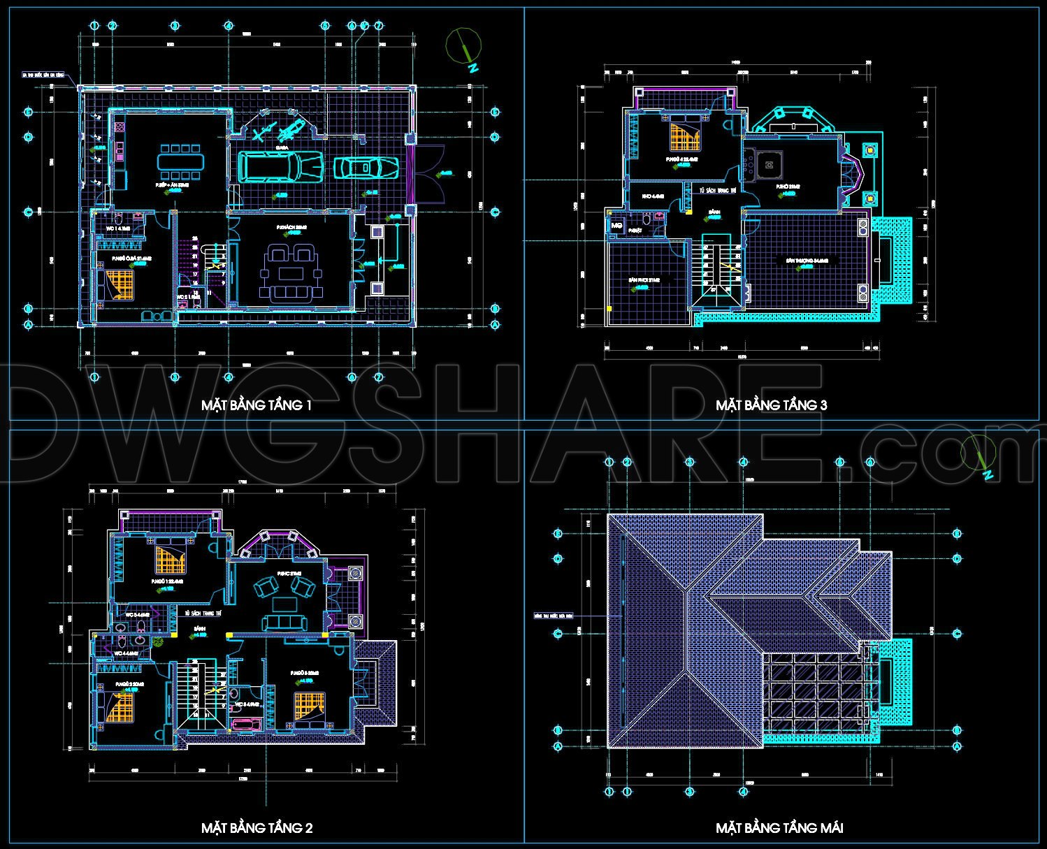
The 3-Story Neoclassical Villa CAD drawings offer a comprehensive view into the design intricacies of a sophisticated architectural masterpiece. These detailed drawings, with a footprint of 13.5 by 18.8 meters, provide essential documentation including floor plans, roof plans, and elevations, each intricately crafted to reflect the neoclassical style.
Beginning with the architectural floor plans, these CAD files lay out each of the villa’s three stories with precision. The ground floor includes a grand entrance leading to spacious living areas and a modern kitchen, ensuring both functionality and aesthetic appeal. The second floor is dedicated to private spaces, offering multiple bedrooms and en-suite bathrooms, laid out to maximize comfort and privacy. The top floor features additional rooms, including a versatile open space that can serve various residential needs, completing the vertical elevation with a sense of harmony and balance.
The roof plan showcases the villa’s complex roofline, characterized by elegant shapes typical of neoclassical architecture. This plan is essential for understanding drainage, insulation, and aesthetic alignment with the villa’s overall design.
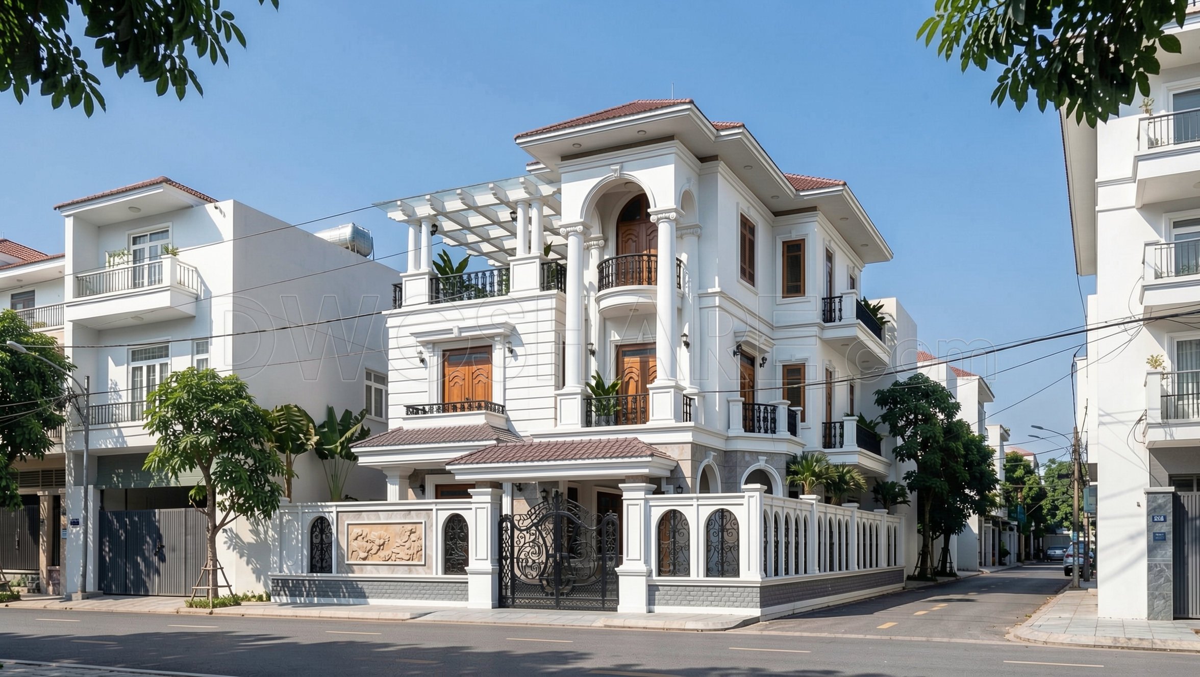
Turning to the elevations and sections, these drawings provide critical insights into the external appearance of the villa, highlighting key neoclassical features such as symmetrical lines, decorative elements, and the interplay of light and shadow on the structure’s façade. These sections are crucial for both architects and builders, allowing them to visualize the construction process and ensure that the design theory translates into reality seamlessly.
The grid lines, dimensions, and level markers included in these drawings offer precise measurements and alignment cues, pivotal for architects during design development and crucial for construction teams to ensure accuracy on-site. This level of detail aids in reducing errors, optimizing costs, and enhancing coordination between design and construction phases.
These CAD DWG files are a valuable resource, boasting high technical accuracy and easy modification, allowing for adaptation in AutoCAD for personalized design needs. They are freely shared for design reference, study, and as a foundational base for detailed technical drawing development, providing architects, interior designers, and students with an exemplary resource for inspiration and practical application.
I also recommend downloading other Houses CAD drawings for your project reference.
- File format: .DWG
- Size: 482 KB
- Source: DWGshare
- AutoCAD platform 2018 and later versions. For downloading files there is no need to go through the registration process
If you find our work useful, your support would mean a lot and help us grow even better.DONATE
Related posts
542. Neoclassical Villa 13 × 15 m – 3-Story House Plans DWG
497. Download CAD Design Drawings for a 6-Story House with Dimensions 6m x 20m
4-Story House a Complete Project AutoCAD File 11mx23m
303. CAD design drawings for a 3-story townhouse with dimensions of 4.5m x 17.2m
607. 3-Story Modern Gable House 8.5 × 11.5 m – Floor Plans & Elevation CAD Drawing
290. CAD design drawings for a 3-story townhouse with dimensions of 5m x 10m
331. CAD design drawings for a 3-story townhouse with dimensions of 5m x 21.2m
Autocad Drawings Of 3-Story Modern House 7m x9m For Download
Autocad Drawing Of 5-Story Classic Villa 9.6mx13.9m For Download