
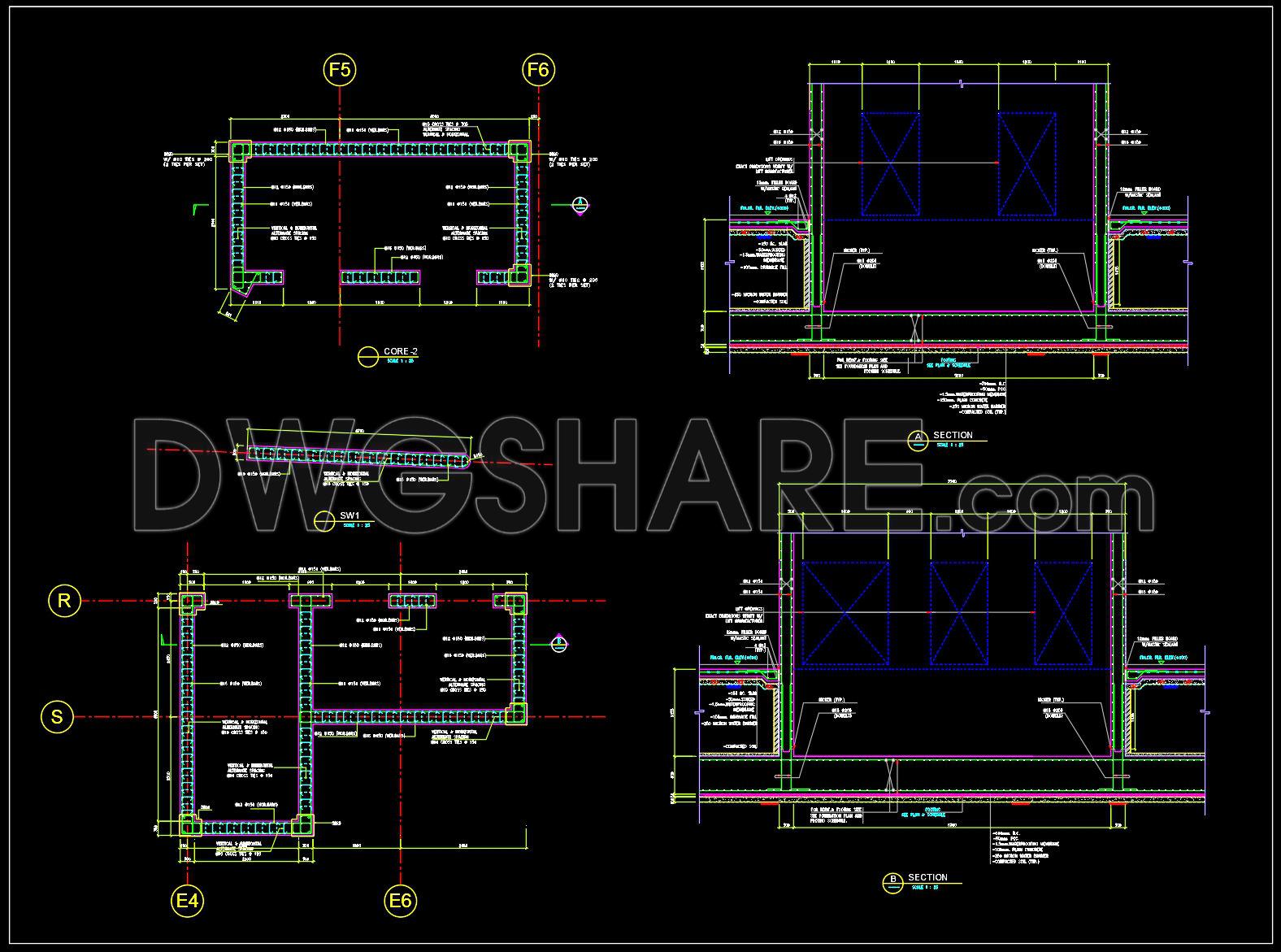
723. Reinforced Concrete Shear Wall Design, Sections and Rebar Details CAD Drawing DWG
The illustrated Reinforced Concrete Shear Wall Design CAD drawing showcases a detailed perspective of essential construction components. As a professional in architectural and structural design, these documents serve as fundamental blueprints within the realms of structural engineering and construction management. The drawings are fundamentally structural drawings, which encompass various key elements.
Key features depicted include:
Plan Sections: Display precise layouts and configurations of shear walls, indicating the positioning and dimensions essential for maintaining structural integrity.
Elevations and Sections: These views provide critical insights into the physical appearance and functionality of the constructed elements, allowing for a comprehensive understanding of the wall configurations at varying heights and sections.
Rebar Details: Essential for the effective reinforcement of concrete structures, the detailed rebar arrangements demonstrated in the drawings ensure the walls can efficiently handle applied stresses.
Grid Lines, Dimensions, and Level Markers: Clearly outlined to aid in the precise positioning of structural components within the overall design, ensuring accuracy during on-site construction.
These structural drawings are indispensable in the practical execution of architectural designs. Each component serves a distinct purpose: the functional layout aids architects during the design development phase, while interior designers use technical details for compatibility with aesthetic elements. For construction teams, these drawings are pivotal, providing necessary reference points for accurate execution and coordination among different construction disciplines.
Architects and construction professionals draw immense value from these CAD drawings due to their high technical accuracy and adaptability. The files are easily modifiable in AutoCAD, allowing for quick alterations and versioning, enhancing coordination between design and construction teams, and minimizing errors. Such efficiency not only streamlines the building process but also optimizes costs.
Furthermore, these CAD DWG files are available free of charge and are an excellent resource for various applications, including design reference, academic study, and as foundational bases for developing further technical drawings. The availability of these resources encourages innovation and learning, aiding both seasoned professionals and students in enhancing their craft.
I also recommend downloading other Cad Details CAD drawings for your project reference.
- File format: .DWG
- Size: 322 KB
- Source: DWGshare
- AutoCAD platform 2018 and later versions. For downloading files there is no need to go through the registration process
If you find our work useful, your support would mean a lot and help us grow even better.DONATE
Related posts
746. Stilling Basin Concrete Layout & Cross Sections – Free DWG Download
180. CAD drawing Of Steel Building Free download
626. Free CAD Drawings of Concrete Bridge Piers and Footing Details
41.Cladding Weld Detail LMW CAD
385. Free Download of Structural CAD Drawings for 12.4m x 16.1m Reinforced Concrete Townhouse
318. Download free CAD structural drawings for a 4m x 18.5m reinforced concrete townhouse construction
302. Structural Drawings Of 2-Story House A Complete Project 6m x 20m For Download
78.Autocad Drawings Of Retaining Wall Concrete Reinforcement Details For Download
181. CAD drawing Steel Building 3D Template Free Download