
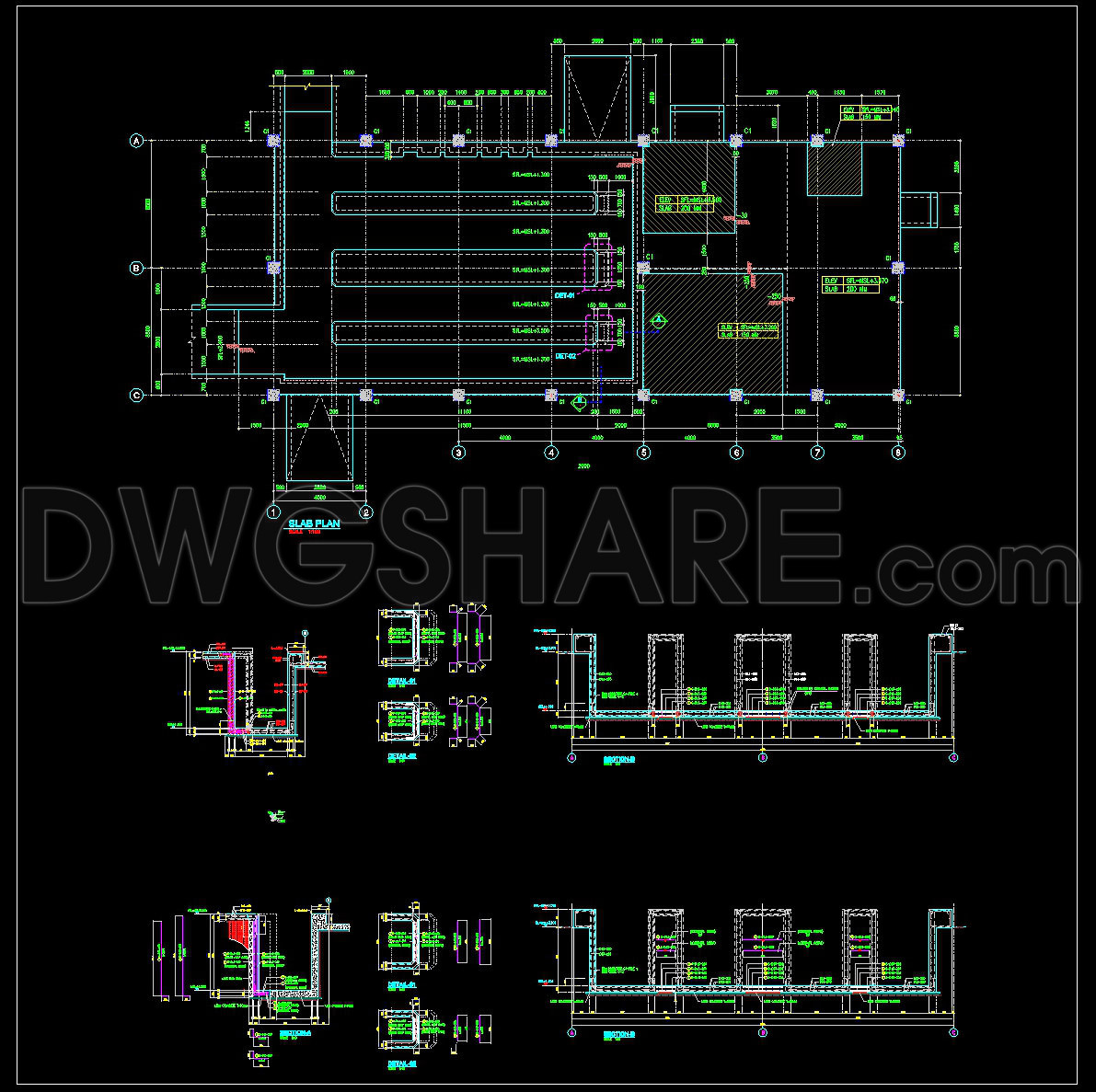
765. Standard Concrete Wall Trench Reinforcement Details CAD DWG
The Standard Concrete Wall Trench Reinforcement Details CAD drawings provide a comprehensive look into the structural components essential for building stable and resilient constructions. These structural drawings are essential in developing a clear understanding of how concrete walls are reinforced within a trench system, a critical aspect of modern architectural projects.
At the forefront of this set is a detailed plan layout which outlines the grid lines, dimensions, and level markers. This plan is meticulously crafted to ensure structural accuracy and practical implementation on-site. The grid lines provide a framework that aids in precise placement and alignment, crucial for maintaining the integrity of the construction throughout its lifecycle.
Also included are section views that delve deeper into the specifics of the trench reinforcement. These sections highlight the arrangement of rebar and other reinforcement materials, offering insight into their positioning and spacing. This level of detail is imperative for construction teams, ensuring that reinforcement is executed correctly for optimal strength and durability.
The inclusion of detailed construction drawings adds another layer of practical value. These schematics showcase the finer aspects of joining and support structures within the trench walls. By presenting every element, from rebar hooks to concrete fills, these drawings enable on-site teams to understand fully how each piece contributes to the overall structural cohesion.
From the perspective of designers and architects, these CAD files provide several advantages. The high technical accuracy displayed throughout the drawings facilitates seamless modifications and adaptability, crucial during the design development phase. Architects can utilize these files to experiment with variations while maintaining structural integrity, which enhances overall design efficiency.
For construction teams, the availability of such precise drawings leads to improved coordination between the design and construction processes. With every dimension and level indicated, error margins are considerably minimized, resulting in cost optimization and reduced material waste.
The Standard Concrete Wall Trench Reinforcement Details CAD DWG files are accessible for free, making them an invaluable resource for design reference, academic study, or as a foundational base for developing technical drafts. The ability to reuse and alter these files in AutoCAD ensures they are not just static resources, but dynamic tools adaptable to various project needs.
In summary, these CAD drawings are an essential resource, seamlessly integrating design precision with real-world application. They empower professionals across architecture, engineering, and construction to collaborate effectively, ensuring projects are executed with competence and innovation.
I also recommend downloading other Cad Details CAD drawings for your project reference.
- File format: .DWG
- Size: 4 MB
- Source: DWGshare
- AutoCAD platform 2018 and later versions. For downloading files there is no need to go through the registration process
If you find our work useful, your support would mean a lot and help us grow even better.DONATE
Related posts
567. Download free CAD detail drawings of living room interior elevation decorations
748. Storage Hangar CAD Drawings – Layout & Elevation Details
545. Free CAD Drawing – Hotel Swimming Pool Floor Plan Layout
273. Detailed architectural CAD drawings of the balcony and entrance steps of the townhouse
177.Autocad drawing of detailed foyer entrance facade of the house for download
24.Gantry Crane General Drawing CAD
17.Cad Details Blocks free download
100.Structural Drawing for residential house
336. Detailed architectural CAD drawings of the facade townhouse