

851. Architectural CAD Detail – Glass Partition with Timber Louvers System
Advertisements
851. Architectural CAD Detail – Glass Partition with Timber Louvers System
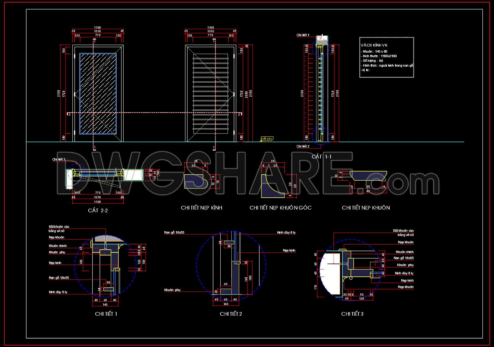
The architectural CAD detail drawing in question is a comprehensive representation of a glass partition with a timber louvers system. Offering an intricate view of this design, the CAD drawing includes multiple detailed components presented in both section views and detail drawings. This provides a clear visualization of how the glass partition integrates with the timber louvers, highlighting the technical precision necessary for effective design and construction implementation.
At the forefront, the drawing features detailed sections and elevations. These views are fundamental, as they give a vertical cut-through of the assembly, which reveals the spatial arrangement and interrelationship between the glass panels and timber louvers. Dimensions are meticulously annotated, offering precise measurements essential for construction accuracy. Noteworthy are the grid lines and level markers, which play an integral role in ensuring alignment and balance in the overall design.
Component details captured in the drawings include:
– Sectional views (Cuts 1-1 and 2-2) illustrating the integration between glass panels and louvers
– Frame and louver connection details showcasing the attachment and alignment mechanisms
– Glass thickness specifications, which inform material selection and structural considerations
– Louver dimensions and spacing, ensuring aesthetic consistency and functional performance
These drawing types serve multiple purposes in real-world applications. For architects, they provide a crucial tool during design development, allowing them to refine and adapt the aesthetic and functional elements of the design. Interior designers rely on these precise details to prepare technical drawings essential for specifying materials and finishes.
Moreover, the construction teams benefit significantly from these drawings. The high level of technical accuracy ensures seamless coordination during construction phases, which reduces errors and optimizes costs. The clarity and precision provided allow for effortless modification and reuse in AutoCAD, streamlining adjustments as needed throughout the building process. These advantages underscore the practical value these drawings offer to both design and construction professionals.
The availability of these CAD DWG files for free makes them a valuable resource for design reference and research purposes. They offer an excellent base for technical drawing development, supporting both educational initiatives and practical implementations in architectural practice.
I also recommend downloading other Cad Details CAD drawings for your project reference.
- File format: .DWG
- Size: 151 KB
- Source: DWGshare
- AutoCAD platform 2018 and later versions. For downloading files there is no need to go through the registration process
Advertisements