
855. Architectural CAD Drawings of a Two-Storey Residential House Design
These architectural CAD drawings provide an in-depth view of a thoughtfully designed two-storey residential house. The drawings encompass a comprehensive array of essential components, ideal for both architects and construction professionals. Let’s delve into the specific drawing types and their applications in both design and construction phases.
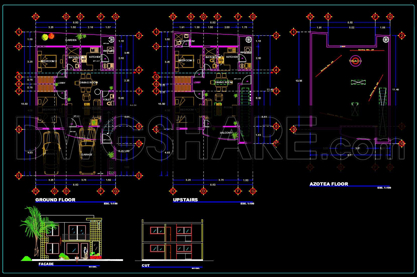
The functional floor plan layout is depicted across the ground floor, upstairs, and azotea floor illustrations, supporting seamless planning and communication. The ground floor reveals a meticulous arrangement including a garage, lobby, dining room, two bedrooms, kitchen, bathroom, and even a snug garden area, all marked with clear grids, dimensions, and level markers. The presence of these markers ensures straightforward interpretation and construction accuracy.
Moving to the upstairs layout, it similarly mirrors the organized spatial allocation with additional living spaces like bedrooms, a balcony, and service areas such as another bathroom and kitchen. The azotea floor drawing exhibits the roof layout, essential for understanding the structural footprint and any additional rooftop facilities, completing the vertical ascension of the design.
Complementing these layouts are the elevations and sections provided. These include the facade and a cut section, both instrumental in visualizing exterior aesthetics and interior structuring. The facade elevation, rich in details, assists architects in refining external finishes, while the section offers a cross-sectional view, crucial for understanding the spatial relationship between various storeys and components.
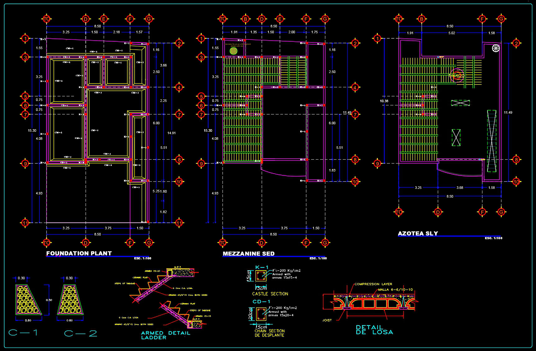
Detail drawings such as the foundation plan, armed detail ladder, and detailed sections like castle and chain sections provide insights into specific construction elements. These are invaluable for guiding the structural integrity and support strategy, defining how various construction components unify to ensure safety and functionality.
For professionals employing these sheets, the CAD files offer exceptional practicality; they are easily modifiable in AutoCAD, ensuring adaptivity to design changes, and also enhance coordination during construction phases. With high technical accuracy, they are designed to minimize errors and provide cost-effective construction solutions. Architects can leverage these drawings during the design development stages, while construction teams use them for on-site reference and precision.
These drawings, shared freely, serve as an excellent base for design reference, study, and further technical drawing development. They exemplify efficiency and clarity, which is imperative for successful architectural planning and execution.
I also recommend downloading other Houses CAD drawings for your project reference.
- File format: .DWG
- Size: 1 MB
- Source: DWGshare
- AutoCAD platform 2018 and later versions. For downloading files there is no need to go through the registration process
If you find our work useful, your support would mean a lot and help us grow even better.DONATE
Related posts
830. Download CAD Drawings of a 1-Story Villa with 3 Bedrooms (28m x 49m)
524. 3-Story House Concept Design – Floor Plans, Elevations, Sections & Roof Plan CAD DWG
545. Modern Villa 28 × 26 m – 2-Story Architectural Plans DWG
4 Bedrooms Two Storey House Autocad Plan Free Download
309. CAD design drawings for a 4-story townhouse with dimensions of 6m x 15m
Autocad Drawings Of 4-Story House Plans, Elevations And Sections 8×14.5m For Download
260. The CAD drawings of the floor plan, elevation, and cross-sections of the 3-story house with dimensions of 5.5m x 15.9m
Drawing Of 7-Story House A Complete Project 8.9m x 10.1m For Download
333. CAD design drawings for a 3-story townhouse with dimensions of 6m x 16m