
474. Elevator Layout, Shaft Sections and Installation Details
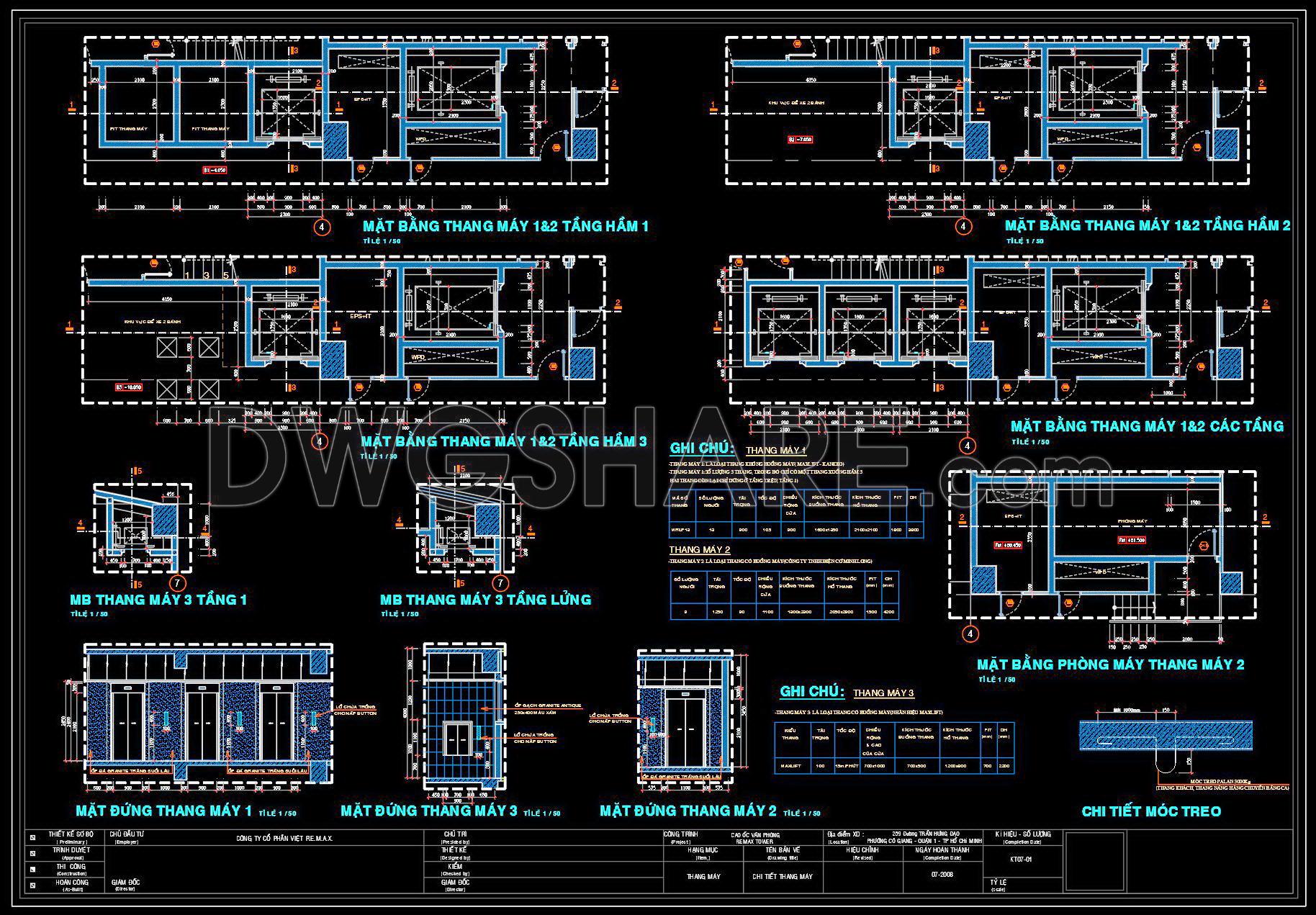
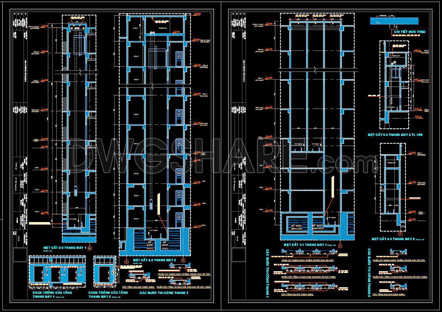
The CAD drawings under review represent a comprehensive exploration of elevator layout, shaft sections, and installation details, essential components in architectural and urban planning projects. These architectural floor plans and section drawings are crucial for the successful integration of vertical transportation solutions within a building’s infrastructure. Detailing components such as shaft sections, floor layouts, and installation specifics, these drawings are indispensable for architects, civil engineers, and construction professionals.
The drawings include a variety of specialized views and details, each meticulously drawn to support both design verification and construction execution. Key elements visible in the provided CAD files are:
Detailed floor plans for different levels
Cross-section views illustrating shaft configurations
Installation details for elevator shafts and cabin placements
Precise grid lines and dimension annotations
These elevator layout and installation detail drawings are particularly beneficial in the design development phase, offering architects a clear geometric understanding of the spatial requirements and structural implications of elevator installation. By using these detailed plans, interior designers can better coordinate shaft placements with interior layouts to optimize space usage and enhance functionality.
For construction teams, these drawings provide indispensable reference points. They ensure precise installation of elevator components, reducing potential construction errors and leading to cost efficiency. The emphasis on high technical accuracy within the drawings facilitates seamless coordination between design and execution, enabling modifications and updates in AutoCAD with ease.
Practically, shaft sections and installation details are pivotal in verifying that constructed elements adhere strictly to design specifications. This reduces on-site errors and supports a smooth transition from design to built environments, crucial for maintaining project timelines and quality.
Moreover, these CAD DWG files are generously shared for free, making them a valuable resource for design reference, academic study, and developing technical drawings. Their availability encourages broader learning and application, aiding both seasoned professionals and emerging architects in exploring real-world construction and design scenarios.
In summary, the elevator layout, shaft sections, and installation details CAD drawings are a robust tool in facilitating design precision and construction efficacy. By ensuring detailed coordination and providing comprehensive documentation, these drawings underpin successful architectural and construction project outcomes.
I also recommend downloading other Stairs CAD drawings for your project reference.
- File format: .DWG
- Size: 1 MB
- Source: DWGshare
- AutoCAD platform 2018 and later versions. For downloading files there is no need to go through the registration process
If you find our work useful, your support would mean a lot and help us grow even better.DONATE
Related posts
444. High-Rise Building Staircase CAD Design – Detailed Sections, Floor Plans and Handrail Details
19.Railing AutoCAD file free download
116.Free Download Of 3D Ladder Type 1,2,3 Cad Drawing DWG
71.Details handrail stairs, handrails autocad free download
302. Free Download detailed CAD drawings of townhouse stairs
247. Download detailed CAD drawings of townhouse stairs
167. Download detailed CAD drawings of townhouse stairs
303. Free Download detailed CAD drawings of townhouse stairs
112.Detailed drawings of Spiral Staircase in autocad file