
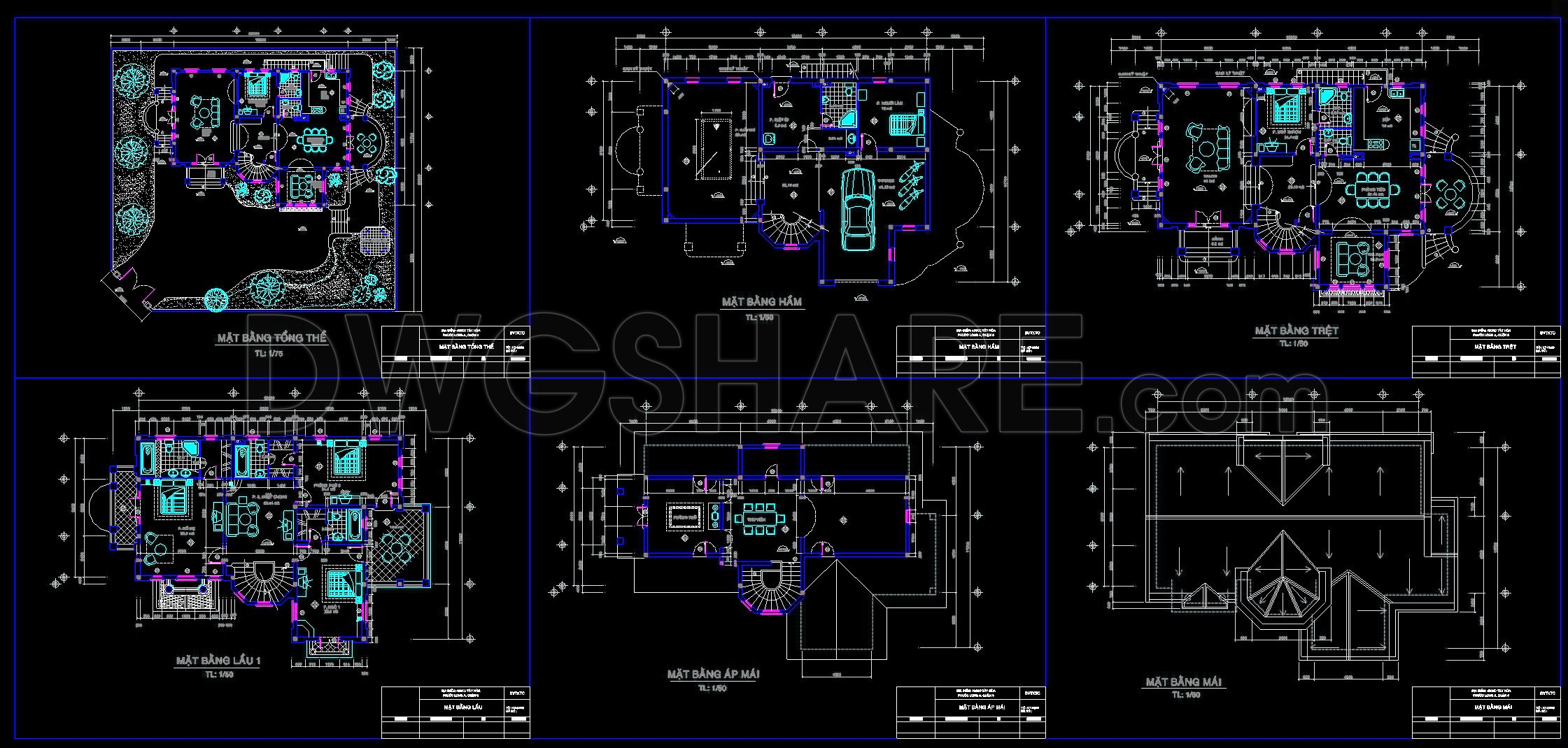
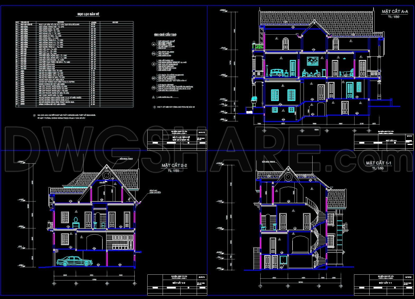
559. Luxury Classic Villa 18 × 12 m – 3-Story Architectural Drawings
The Luxury Classic Villa 18 × 12 m presents a remarkable set of architectural drawings emphasizing precision in design and functionality. This comprehensive CAD DWG collection offers a detailed portrayal of a three-story luxury villa, catering to architects, interior designers, and construction professionals seeking high-level technical documentation.
The set includes:
Functional floor plan layouts: These plans map out the spatial organization across three floors, highlighting room placements, circulation paths, and essential architectural elements. They provide the foundational guide for architects during the design development phase. Each floor reveals distinct zones, accommodating living areas, bedrooms, and service spaces, ensuring optimal layout efficiency.
Elevations and sections: Depicting the villa’s exterior and cross-sectional perspectives, these drawings offer insights into the building’s facade articulation and vertical space distribution. Elevations showcase the classic aesthetic, while sections reveal structural integrity and interior volume dynamics, essential for both architectural design and structural analysis.
Construction detail drawings: Focused on key architectural features, such as staircases and roofing connections, these details are indispensable for contractors and builders during on-site execution. They ensure that every architectural element is built in accordance with design specifications, minimizing construction errors and optimizing cost management.
Grid lines, dimensions, and level markers: Clearly marked across all drawings, these features provide a technical roadmap for project stakeholders. Dimensions ensure precise measurements, while grid lines and level markers guide spatial orientation and alignment, enhancing coordination between design and on-site teams.
These CAD drawings are integral during project planning and execution, offering:
– High technical accuracy: Essential for reducing discrepancies between design intent and construction reality.
– Easy modification and reuse in AutoCAD: Facilitates design adjustments and iterations without compromising on quality.
– Improved coordination between design and construction: Enhances communication among architects, engineers, and builders, supporting seamless project execution.
– Reduced errors and cost optimization: By providing precise details, these drawings help in mitigating project risks and controlling budget.
Available for free, these CAD DWG files are an invaluable resource for design reference, study and research, and serve as a reliable base for further technical drawing development.
I also recommend downloading other Houses CAD drawings for your project reference.
- File format: .DWG
- Size: 2 MB
- Source: DWGshare
- AutoCAD platform 2018 and later versions. For downloading files there is no need to go through the registration process
If you find our work useful, your support would mean a lot and help us grow even better.DONATE
Related posts
Townhouse Villa Model type F AutoCAD File Free Download
291. CAD design drawings for a 3-story townhouse with dimensions of 5m x 17m
146. Free Download of Mechanical and Electrical Construction Design Drawings for a 3-Story House
Autocad Drawing Of 4-Story Classic Villa 8.6mx11.4m For Download
459. 5m x 24.8m 3-Story Townhouse Floor Plans & Elevations CAD DWG
245. Cad Drawings Of 4-Story House Interior layout, floor plan, ceiling plan 12.8m x 17m For Download
3 Stories House Plans and Sections Details AutoCAD File 9.8X15m
256. The CAD drawings of the floor plan, elevation, and cross-sections of the 4-story house with dimensions of 4.5m x 12m
8 Floors Apartment building PDF File Free Download