
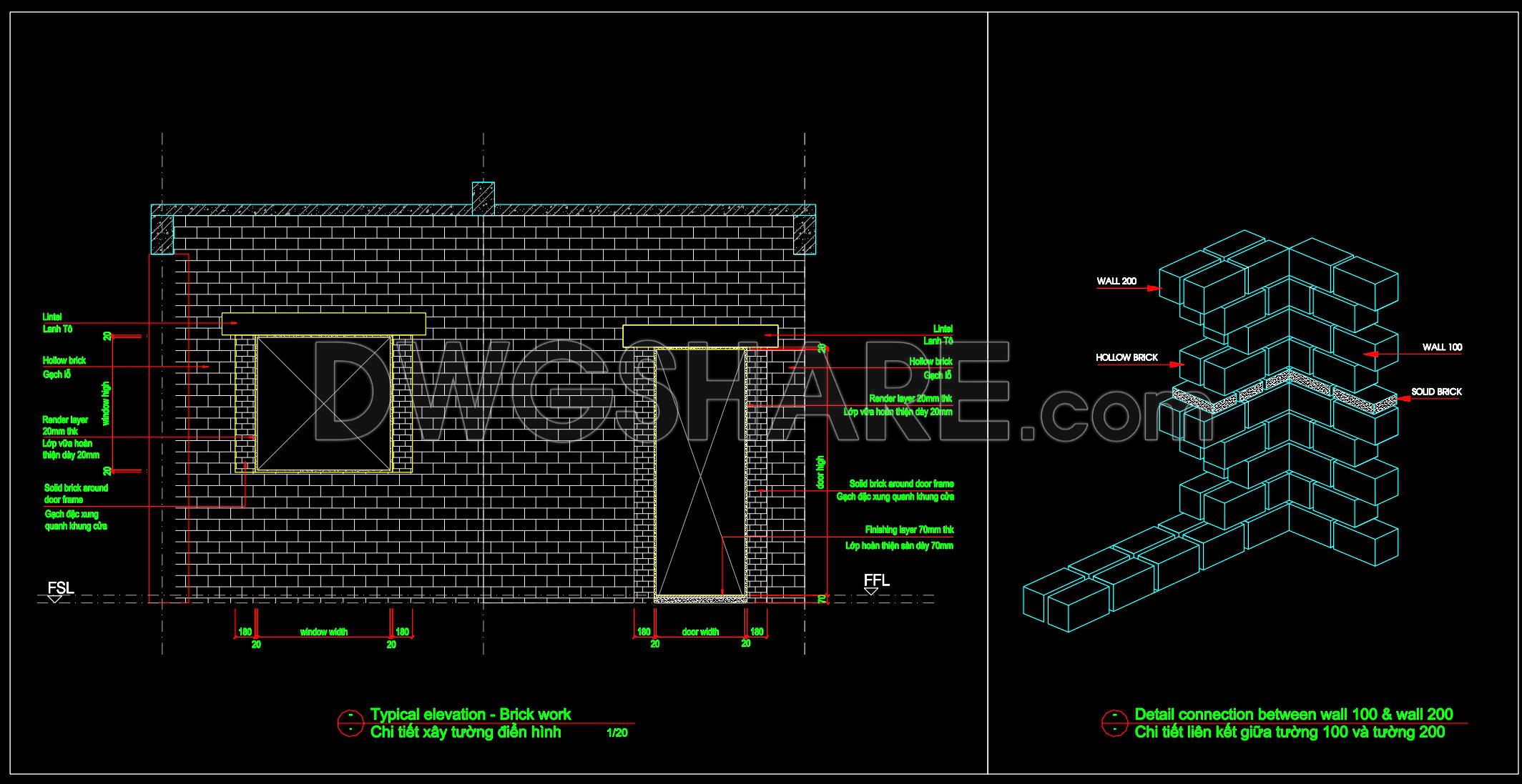
600. Typical Brick Wall Construction Detail CAD Drawing
The Typical Brick Wall Construction Detail CAD Drawing is a comprehensive guide for professionals seeking clarity in masonry design and construction. This detail drawing offers a precise architectural illustration showcasing the complexity and intricacy of brick wall construction.
The drawing includes several key components, essential for a thorough understanding and execution of brick wall projects. Key elements illustrated in the CAD file include:
Elevation View: This part of the drawing displays a detailed elevation of the brick wall, providing crucial insights into height and architectural design. It outlines the arrangement of bricks, window openings, and essential specifications like lintels, hollow bricks, and solid brick surrounds.
Sectional Details: Sections are meticulously drawn to depict the various layers involved in construction. These include the render layer of 20mm thickness, essential for finishing, and the additional finishing layer at 70mm, providing durability and aesthetic appeal to the wall structure.
Connection Details: A significant highlight of this CAD drawing is the detailed depiction of the junction between different wall thicknesses, specifically between Wall 100 and Wall 200. Understanding these connections is vital for ensuring structural integrity and achieving seamless transitions.
Dimensional Annotations and Labels: The document includes detailed annotations for precise construction execution. Dimensions for window width, door width, and space allowances are clearly marked, facilitating accurate on-site measurements and adjustments.
This set of construction detail drawings plays a pivotal role in both design development and construction implementation. Architects utilize these CAD drawings to refine their design plans, providing a clear visual reference that enhances communication with clients and construction teams. For interior designers, these specifications serve as a baseline for preparing technical details that align with the overall architectural context.
Furthermore, for construction teams, these CAD drawings are invaluable. They offer accurate, ready-to-use templates that significantly reduce the likelihood of errors on-site, streamlining the construction process, and optimizing costs. The availability of these files in AutoCAD format ensures they are easily modifiable and can be reused across different projects, enhancing their value in professional practice.
Typical Brick Wall Construction Detail CAD files are shared freely, providing immense benefit as a design reference, educational tool, or a template for technical drawing development. Such resources are instrumental for students and professionals aiming to deepen their expertise in architectural design and masonry work.
I also recommend downloading other Cad Details CAD drawings for your project reference.
- File format: .DWG
- Size: 117 KB
- Source: DWGshare
- AutoCAD platform 2018 and later versions. For downloading files there is no need to go through the registration process
If you find our work useful, your support would mean a lot and help us grow even better.DONATE
Related posts
174.Detailed AutoCAD drawings of vertical elevations and classic balconies
538. Free Download – CAD Detail Drawing of Ramp, Drainage Pit, and Railing System
594. Free CAD Drawings of Balcony Detail – Plans, Sections & Railing Design
224. Detailed CAD drawings of vertical facades in classical architecture
280. Detailed CAD drawings of the facade and classical ornaments for the townhouse
25.Autocad Mortise and tenon detail Blocks free download
116.Classical Architectural details Blocks free download
138.Classical Architectural details Blocks free download
64.Kitchen Cabinet Details Autocad Blocks