
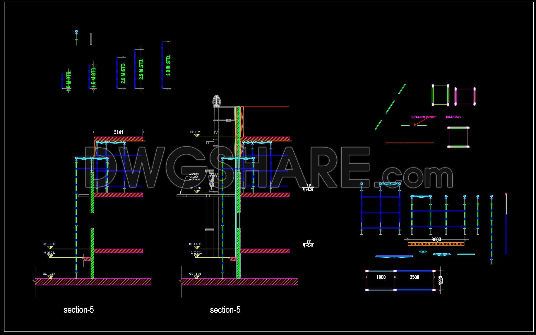
721. Scaffolding Components, Connections and Assembly Details CAD Drawing DWG
In the realm of architectural design and construction, scaffolding components and assembly details play a crucial role in ensuring both safety and efficiency on site. This structural drawing provides a comprehensive look into the intricacies of scaffolding systems, crucial for professionals overseeing the construction phase of projects.
The drawing type presented here is a detailed section and elevation view of scaffolding components, meticulously illustrating how various elements come together in the physical space. Here, you will find components such as upright supports, bracing elements, and planks clearly depicted. Each part is methodically labeled with dimensions, allowing for precise calculations and placements. Among the visible features are:
- Section views displaying the height and connection points of scaffolding parts
- Elevation views showcasing the alignment and relationship between different scaffold sections
- Detailed connection drawings highlighting how the parts are securely joined
- Dimension lines providing accurate measurements for construction team reference
These drawings serve as an indispensable tool in the architectural documentation process. Architects rely on them during the design phase to assess the practical aspects of deploying scaffolding on site, ensuring that they fit seamlessly into the overall project plan. For interior designers, these details are critical when modifying or planning spaces, impacting how areas are accessed during construction phases.
The practical uses extend to construction teams, where the drawings become a blueprint for on-site setup, ensuring alignment with safety standards and structural integrity guidelines. With dimensions clearly marked, the likelihood of errors diminishes, leading to cost-effective and timely construction processes.
Furthermore, the high technical accuracy of these drawings allows for easy modification within software like AutoCAD, streamlining updates and changes that often occur during project development. This ease of manipulation reduces overall coordination time between design and construction teams, ultimately optimizing resource allocation and site execution strategies.
These CAD DWG files, offered at no cost, are an invaluable resource for design reference, academic study, and as a foundational base for further technical drawing development. By utilizing these precise documentation tools, professionals in architecture and construction can significantly boost the quality and efficacy of their projects.
I also recommend downloading other Structural Details for your project reference.
- File format: .DWG
- Size: 1 MB
- Source: DWGshare
- AutoCAD platform 2018 and later versions. For downloading files there is no need to go through the registration process
If you find our work useful, your support would mean a lot and help us grow even better.DONATE
Related posts
445. Free Download CAD Drawings of Reinforced Concrete Wall Structure Plans for Buildings
235. Structural Drawings Of 3-Story House A Complete Project 6.5m x 13.6m For Download
432. Download of Structural CAD Drawings for 11.2m x 14.8m Reinforced Concrete Townhouse
619. Free Download Cheese Factory Layout & Architectural Plans CAD DWG
168. Cad Drawing Of Wooden Fence Elevation and Section Details
630. Free Essential CAD Template Containment Wall Elevations and Sections
246. Structural Drawings Of 2-Story House A Complete Project 8.7m x 13.5m For Download
378. Free Download of Structural CAD Drawings for 15m x 16m Reinforced Concrete Townhouse
760. Professional Beam Drilling CAD Template DWG for Structural Design