
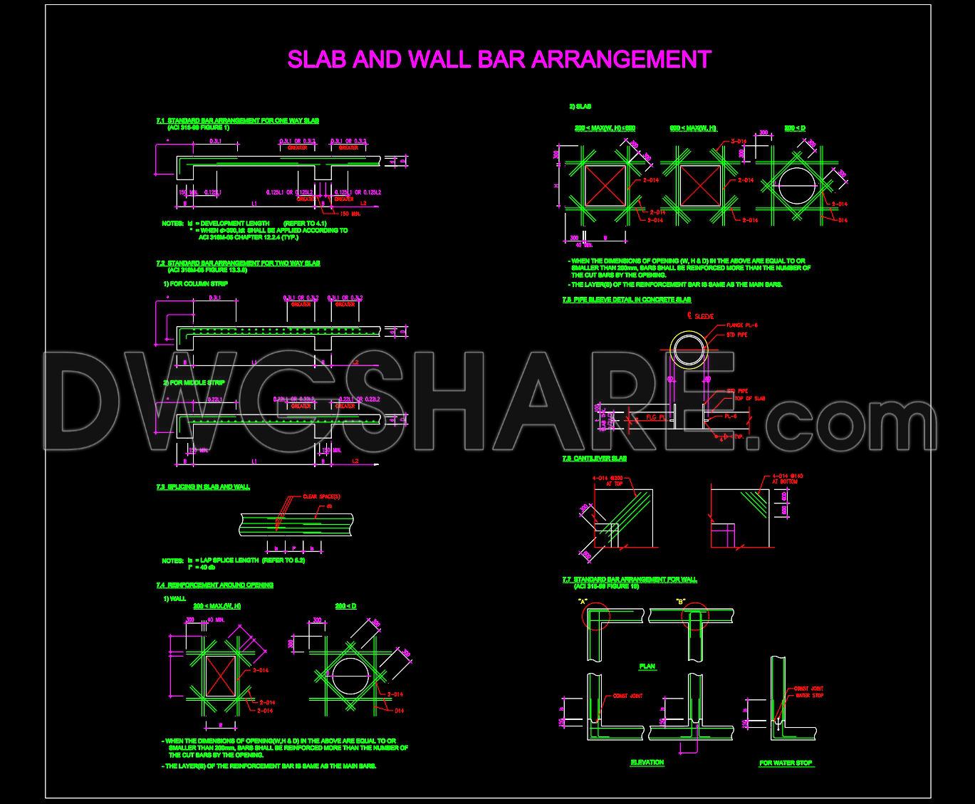
730. Standard Slab and Wall Reinforcement Details CAD Drawings DWG
The standard slab and wall reinforcement details CAD drawings presented in this set provide invaluable resources for professionals engaged in architectural and structural design. As a critical component of construction documentation, these structural drawings outline the precise arrangement and specifications for reinforcing bars used in slabs and walls, essential for ensuring structural integrity and compliance with building codes.
At the heart of these drawings are the meticulously detailed arrangements that include specific placement of reinforcement bars, vital for both slab and wall construction. In these plans, you’ll find several key components:
Detailed reinforcement for one-way slabs, demonstrating precise bar placement to handle structural loads effectively.
Two-way slab reinforcement intricacies, vital for distributing weight evenly across supports.
Column strip and middle strip bar positioning in slabs, ensuring load-bearing efficiency and structural stability.
Standard bar arrangements for walls, highlighting strategies for enhancing wall strength and durability.
Moreover, technical components such as development lengths, lap splice lengths, and openings around reinforcement provide further depth for construction professionals. These details are crucial for ensuring that all elements meet required standards, thereby reducing the risk of structural failure.
Architects use these drawings during the design phase to predict how structural components will behave under various physical conditions, allowing for adjustments before actual construction begins. For interior designers, these details are instrumental in ensuring that the proposed designs will not compromise structural elements, offering reassurance that aesthetics and safety can coexist harmoniously.
From a construction perspective, these drawings serve as an authoritative guide for contractors, ensuring that the build aligns precisely with the design intentions. This enhances coordination between design and construction teams, optimizing timelines and reducing errors that could lead to increased costs.
The CAD DWG files are crafted for high technical accuracy, facilitating easy modification and reuse in AutoCAD – a tool widely respected for its precision and versatility. They are shared free of charge, making them accessible for use as a reference in design projects, scholarly study, or as foundational bases for further technical development.
For those in the field, these drawings represent a wellspring of knowledge and a practical asset, laying the groundwork for safer, more efficient, and more effective building practices.
I also recommend downloading other Structural Details drawings for your project reference.
- File format: .DWG
- Size: 87 KB
- Source: DWGshare
- AutoCAD platform 2018 and later versions. For downloading files there is no need to go through the registration process
If you find our work useful, your support would mean a lot and help us grow even better.DONATE
Related posts
634. High-Quality Curtain Wall Detail CAD Drawing – Free DWG File
737. Standard Reinforcement Details for Frame Girders CAD Drawings DWG
67.Free Download of Steel Sliding Door Details Autocad Drawing DWG
204.Structural Drawings Of 4-Story House A Complete Project 12.3×16.7m For Download
299. Structural Drawings Of 4-Story House A Complete Project 4m x 20m For Download
772. Water Tower CAD Drawing – Elevation, Foundation & Structural Details DWG
150. Cad Drawing Of Tower Crane Raft Foundation Details For Download
125.Autocad Drawing Of Cast In Place Concrete On Slab For Download
368. Free Download of Structural CAD Drawings for 11m x 13m Reinforced Concrete Townhouse