
757. Tower Crane Elevation & Location Details CAD Drawing DWG
The tower crane elevation and location details CAD drawings provide essential visual documentation specifically tailored for construction and architecture professionals. These drawings are crucial in the planning and coordination stages of construction projects, offering precise information about the placement and structural integration of cranes on-site.
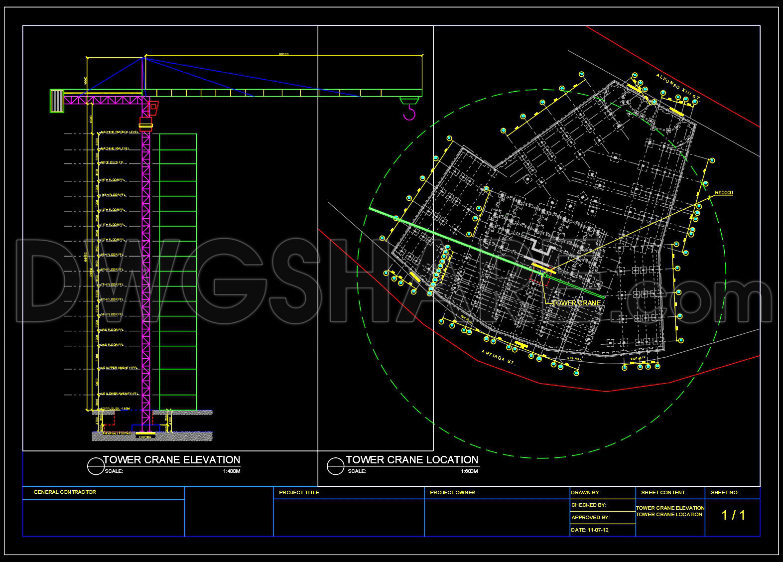
The first set of drawings showcases the tower crane elevation, illustrating the crane’s vertical stature and its alignment with the building structure. This is key for architects and construction teams, as it ensures that the crane is optimally positioned for both safety and efficiency. The elevation view often includes detailed grid lines, level markers, and dimensional data which are indispensable for ensuring that the crane’s height and reach will accommodate the needs of the project without interfering with the surrounding environment.
Alongside the elevation is the tower crane location plan, which provides a horizontal, overhead view of the crane’s footprint relative to the building site. This drawing is particularly useful for project managers and site engineers, allowing them to strategize the crane’s position in relation to roads, other buildings, and construction elements. Key components such as property lines, grid references, and proximity to key structural elements are clearly marked, aiding in accurate site planning and logistical coordination.
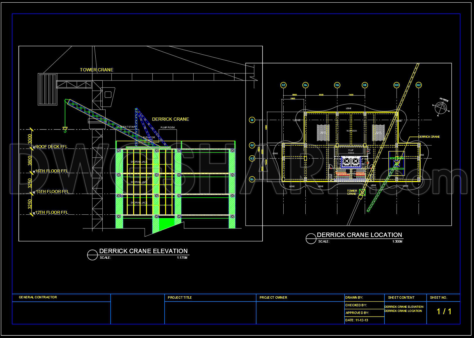
The second set of drawings highlights the derrick crane elevation and location. Similar to the tower crane, these drawings focus on the strategic placement of the derrick crane, often used in combination with tower cranes for enhanced flexibility in material handling. The elevation details provide insight into how the derrick crane is nested among existing structures, crucial for high-rise construction tasks. This ensures that the crane operates within its designed parameters, adhering to safety standards and efficiency goals.
Detailed CAD drawings such as these are invaluable for design development and construction execution. They enable architects to verify design intent during the construction phase and assist construction teams in achieving meticulous accuracy on-site. The high level of detail and specificity offered by CAD DWG files facilitate seamless integration into broader project documentation, enhancing cross-disciplinary communication and reducing the potential for costly errors.
These files are freely available, making them an excellent resource for professionals seeking design references or students researching construction methodologies. They are also suitable as foundational templates for developing technical drawings in AutoCAD, allowing easy modification and adaptation to meet specific project needs.
I also recommend downloading other Transport CAD drawings for your project reference.
- File format: .DWG
- Size: 289 KB
- Source: DWGshare
- AutoCAD platform 2018 and later versions. For downloading files there is no need to go through the registration process
If you find our work useful, your support would mean a lot and help us grow even better.DONATE
Related posts
433. Download of Structural CAD Drawings for 12m x 20.6m Reinforced Concrete Townhouse
315. Download free CAD structural drawings for a 9.7m x 16.8m reinforced concrete townhouse construction
174. CAD drawing Of Grade beam and columns free download
716. Counterfort Retaining Wall Reinforcement CAD Drawing DWG Download
367. Free Download of Structural CAD Drawings for 9.5m x 11.5m Reinforced Concrete Townhouse
18.Colosseum Steel Roof Elevation and Sections Details CAD
171. Details of beams in a project of the University
604. Free Download DWG Templates for Beam Reinforcement Details
323. Free Structural CAD Drawings Available for 4m x 17.4m Reinforced Concrete Townhouse