
215. Water Supply System Design CAD Drawings for Villa (DWG)
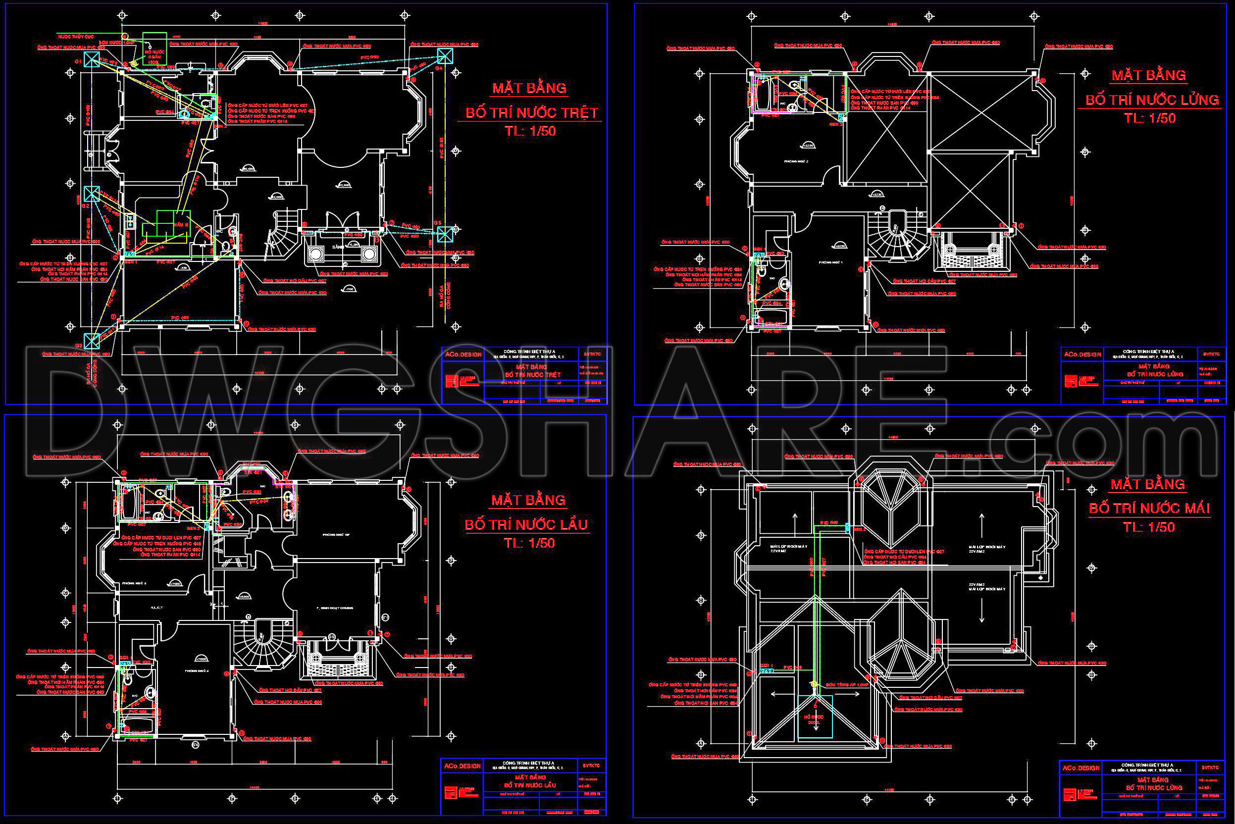
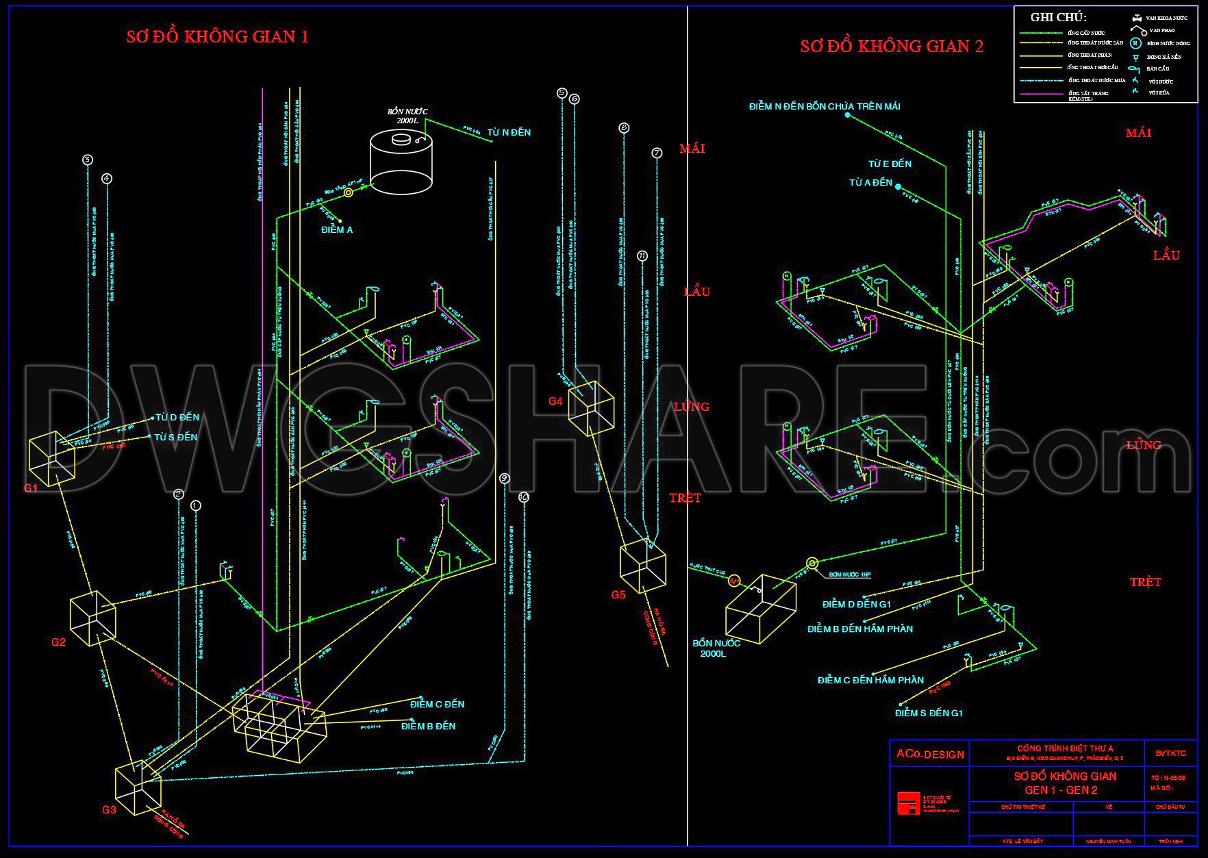
In the realm of architectural planning and design, CAD drawings stand as fundamental tools that offer a comprehensive outlook on the layout and functionality of various systems within a building. The Water Supply System Design CAD Drawings for Villa are a sophisticated collection that presents the intricacies of designing an efficient water supply network for residential structures. These architectural floor plans provide a detailed schematic that is crucial for architects, engineers, and construction teams involved in the development and execution of villa projects.
The primary focus of these drawings is to illustrate a seamless integration of the water supply system within the villa’s architectural framework. Key elements identified in these drawings include:
Functional floor plan layout: Offering an intricate overview of how water systems are mapped out across different levels of the villa, ensuring efficient distribution.
Elevations and sections: These depict the vertical aspects of the water supply lines, emphasizing how they interact with structural components.
Grid lines, dimensions, and level markers: Critical for maintaining accuracy and ensuring all elements align perfectly within the villa’s dimensions.
Each of these components serves vital roles within the design documentation process. Architectural floor plans are meticulously crafted to provide a visual representation of water routes, facilitating both planning and execution. Elevations and sections offer a deeper insight into the vertical integration of supply lines, crucial for assessing the structural integrity and functionality of the water system.
From a practical perspective, these structural drawings are indispensable. Architects utilize them during the design development phase to ensure the systems align with the architectural vision. Interior designers can refer to these plans for harmoniously integrating interior features with the villa’s water system. Construction teams rely heavily on these detailed drawings for coordination and implementation, ensuring each facet of the construction aligns with the planned design.
The technical accuracy of these CAD drawings is paramount. They are readily modifiable, allowing for adjustments and refinements, thus optimizing costs and reducing potential errors during construction. Moreover, they significantly enhance coordination between design teams and construction professionals, establishing a smooth workflow from design to completion.
These CAD DWG files are shared freely online, providing a significant resource for design reference and academic study. They serve as an excellent base for developing technical drawings further, offering a foundational framework upon which various design adaptations and enhancements can be constructed.
I also recommend downloading other Mechanical, Electrical CAD drawings for your project reference.
- File format: .DWG
- Size: 313 KB
- Source: DWGshare
- AutoCAD platform 2018 and later versions. For downloading files there is no need to go through the registration process
If you find our work useful, your support would mean a lot and help us grow even better.DONATE
Related posts
171. Plumbing CAD Drawings DWG – Water Supply & Drainage System
299. Complete Residential HVAC CAD Drawings (DWG) – Air Conditioning, Ventilation and Installation Details
244. 2-Story House Water Supply & Drainage CAD Drawings
182. Complete Residential Water Supply and Drainage System CAD Drawings DWG
149. CAD drawings detailing the design of water supply and drainage systems for a 3-story townhouse
65. CAD drawings for detailed electrical designs for a 3-story townhouse
132. Free download electrical and internet cad drawings for 4-storey house
146. Free Download of Mechanical and Electrical Construction Design Drawings for a 3-Story House
124. CAD drawings detailing the design of water supply and drainage systems for a 2-story townhouse