
594. 3-Story House 9 × 15 m – Ground, Upper Floor, Roof Plans & Elevation CAD Drawing
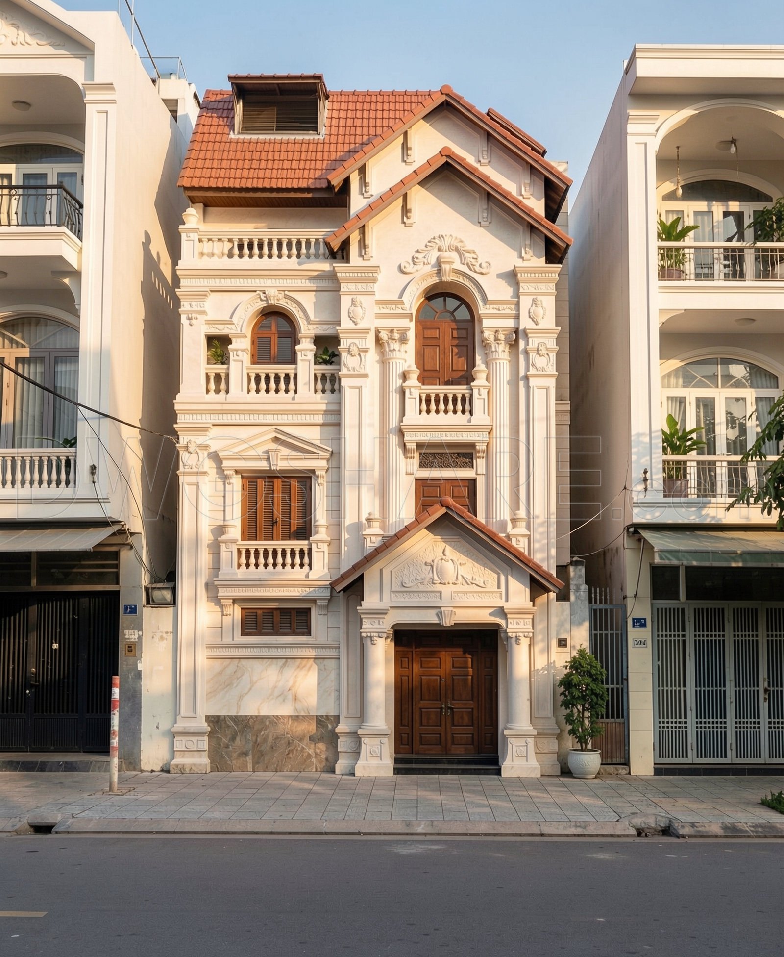
In the realm of architectural and construction planning, detailed architectural floor plans and elevations play an essential role, providing a comprehensive blueprint for the successful realization of a project. The 3-story house measuring 9 × 15 meters showcases an exemplary set of CAD drawings that are profoundly educational for both aspiring and experienced professionals.
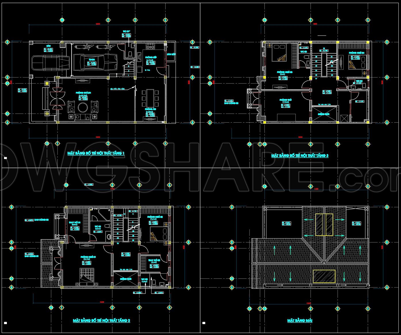
The functional floor plan layout is meticulously detailed across the ground floor, upper floor, and roof, demonstrating efficient space utilization. On the ground level, the plan includes essential living areas, such as a spacious living room, a dining area, and a kitchen, all portrayed with clear spatial delineations. The upper floor follows with private spaces like bedrooms and bathrooms, emphasizing practical layout and accessibility.
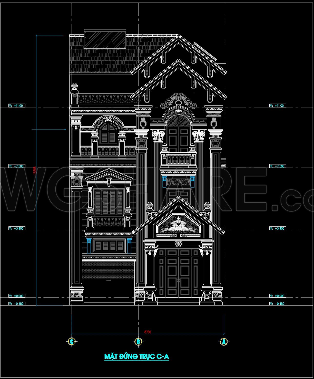
The elevations and sections featured in the drawings highlight the exterior facade, complete with decorative architectural elements that add character and depth. These components are not merely aesthetic but also offer insight into the structural and design elements that maintain harmony in the building’s appearance.
Each drawing is furnished with grid lines, dimensions, and level markers, providing essential technical accuracy necessary for precision in construction. These elements are pivotal during the design development stages for architects, helping to verify that every aspect of the building is correctly proportioned and aligned.
Construction teams rely on these highly accurate CAD drawings to ensure precise coordination on-site, reducing potential errors and optimizing costs. The ease of modification in AutoCAD facilitates adaptability in the design process, allowing architects and builders to make necessary adjustments quickly without starting from scratch.
As these CAD DWG files are shared without charge, they serve as a valuable asset for anyone interested in studying and developing technical drawing skills. They provide a solid foundation for creating custom designs or further exploring architectural software capabilities.
The technical prowess demonstrated in these CAD drawings enhances the synergy between design and construction, fostering a seamless transition from concept to completed structure. These resources are well-suited for use in design reference, study, research, and development of technical drawings, significantly benefitting architecture and construction endeavors.
I also recommend downloading other Houses CAD drawings for your project reference.
- File format: .DWG
- Size: 1 MB
- Source: DWGshare
- AutoCAD platform 2018 and later versions. For downloading files there is no need to go through the registration process
If you find our work useful, your support would mean a lot and help us grow even better.DONATE
Related posts
285. CAD design drawings for a 3-story townhouse with dimensions of 5m x 20m
276. CAD design drawings for a 4-story townhouse with dimensions of 6.1m x 13.2m
527. 3-Story House Concept – 3.9m × 12m CAD DWG
293. Free Download 3-Story House Floor Plan CAD Drawing – 13m x 21m Layout
420. Free Download CAD Design Drawings for a 4-Story House with Dimensions 4.4m x 17.6m
321. CAD design drawings for a 4-story townhouse with dimensions of 5m x 20m
571. Modern 3-Story House 12.5 × 19.2 m – Architectural Plans DWG
295. CAD design drawings for a 6-story townhouse with dimensions of 4.9m x 18.5m
395. Download Architectural CAD Drawings for a 4-Story European Classic Style House (Dimensions: 18.6m x 24.3m)