
725. Shoring Layout and Section Details CAD Drawings DWG
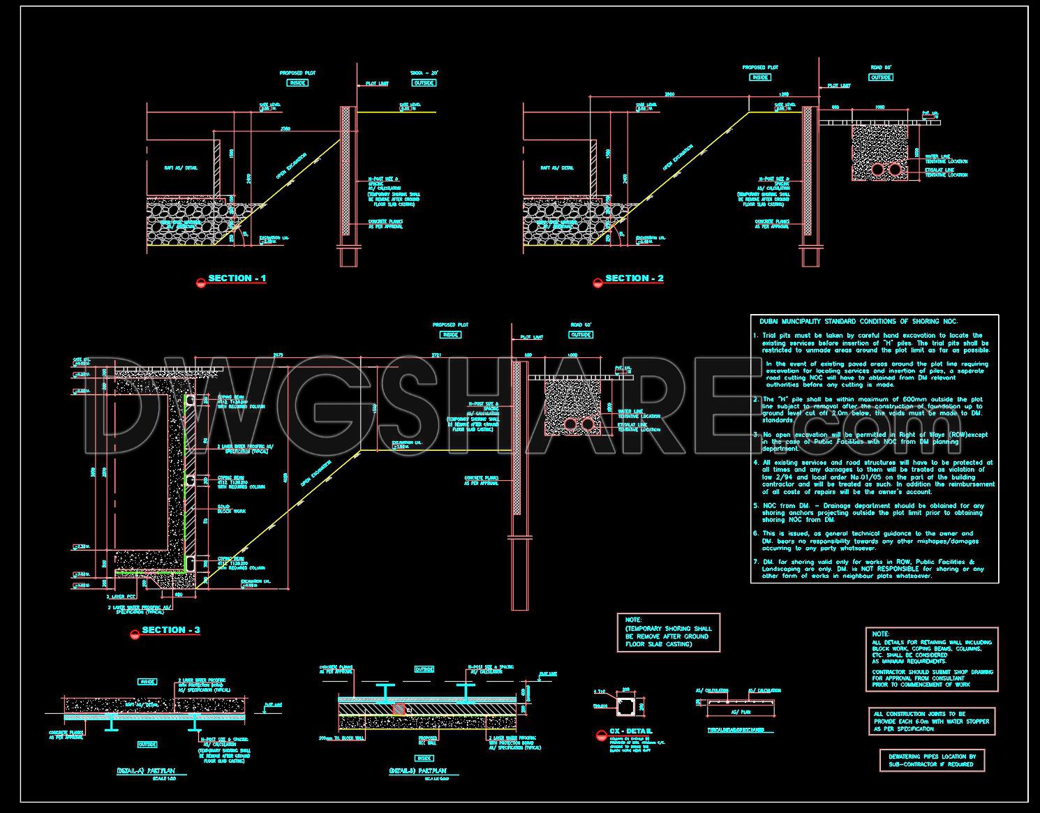
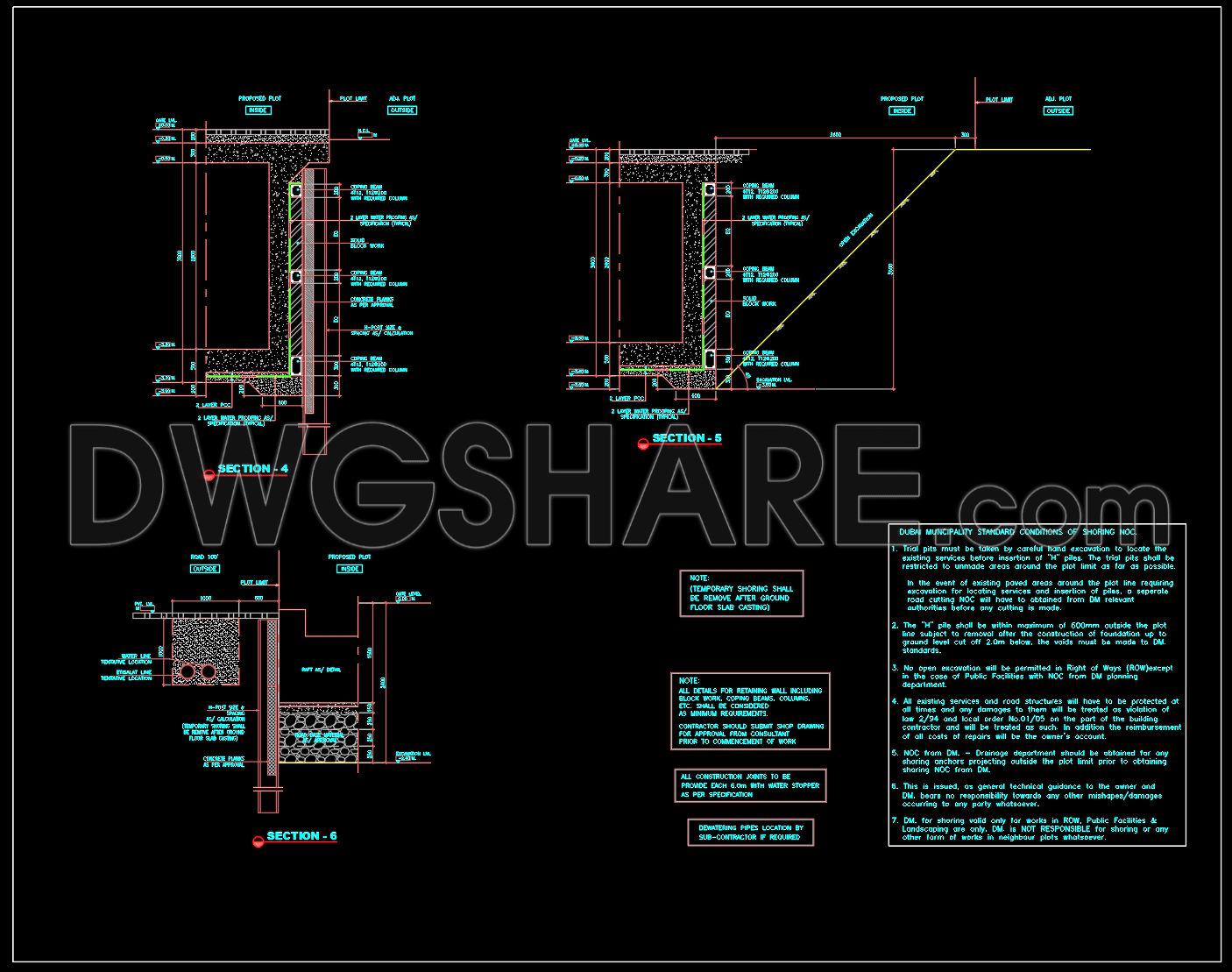
The Shoring Layout and Section Details CAD Drawings provide an indispensable resource for architects, structural engineers, and construction teams involved in the intricate task of designing and constructing robust foundational systems. The DWG files primarily comprise structural drawings, showcasing detailed shoring methodologies vital for ensuring safety and stability in construction projects, particularly those involving deep excavations or nearby structure protection.
At the heart of these CAD drawings are comprehensive section details, essential for visualizing how materials interact and integrate. These include:
Detailed section cuts showing depth and composition of the shoring systems
Specifications of materials used, such as reinforced concrete and steel
Designated grid lines, dimensions, and level markers for precise implementation
Each section drawing is meticulously crafted to illustrate the practical aspects of shoring, focusing on physical constraints and anticipated loads. This focus on details makes these drawings valuable during the design development process, offering architects the ability to iterate designs while ensuring compliance with structural standards. The logical presentation of elements like earth retention systems, bracing, and anchor points allows users to grasp the fundamental aspects of the design swiftly.
Shoring layout plans further enhance these drawings by providing a top-down view of the arrangement and interaction of shoring components. The layout plans perfectly complement the sections, offering a holistic understanding of how theoretical designs translate into functional, on-site structures.
For construction teams, these detailed CAD drawings serve as a blueprint. They facilitate coordination among different building trades, ensuring that everyone works from the same verified documents. This coordination significantly reduces errors and construction setbacks, directly translating to cost savings and adherence to project timelines.
These files are shared for free, providing a rich basis for study and research. One of the standout advantages of these DWG files is their adaptability within AutoCAD, which facilitates easy modifications and updates to suit specific project requirements or location-based regulations. Because of their flexibility, they are perfect for reference in new projects or troubleshooting existing ones, thus ensuring sustained structural integrity and safety.
I also recommend downloading other Structural Details drawings for your project reference.
- File format: .DWG
- Size: 206 KB
- Source: DWGshare
- AutoCAD platform 2018 and later versions. For downloading files there is no need to go through the registration process
If you find our work useful, your support would mean a lot and help us grow even better.DONATE
Related posts
608. Download Free CAD Drawing of Boundary Wall
116.Autocad Drawing Of Elevated Tank Reinforcement Detail For Download
340. Free Download of Structural CAD Drawings for 6m x 17.5m Reinforced Concrete Townhouse
267. Structural Drawings Of 4-Story House A Complete Project 9.7m x 16.8m For Download
693. Oil Tanker Ladder 3D CAD Model DWG – Free Download
670. Ground-Mounted Double-Sided Signboard CAD Drawing (DWG)
381. Free Download of Structural CAD Drawings for 11.4m x 11.7m Reinforced Concrete Townhouse
302. Structural Drawings Of 2-Story House A Complete Project 6m x 20m For Download
333. Free Download of Structural CAD Drawings for 5m x 14m Reinforced Concrete Townhouse