
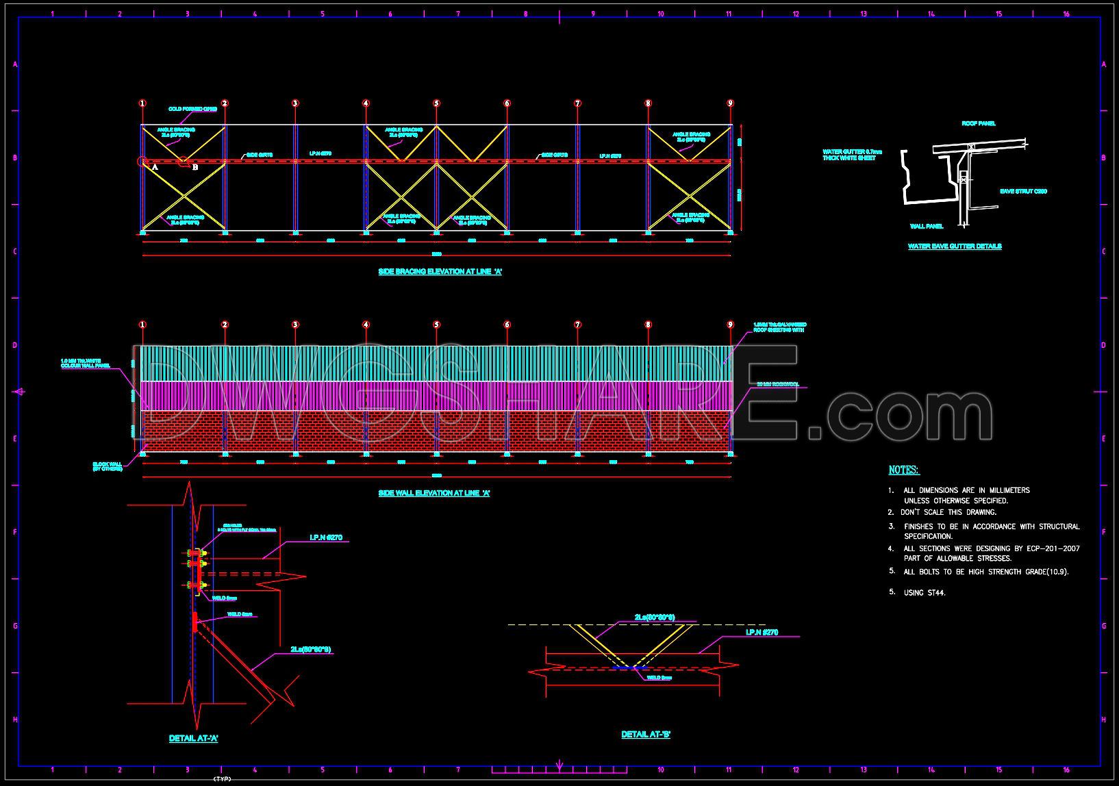
728. Side Wall Elevation and Bracing Details CAD Drawings DWG
In the realm of architectural and structural design, side wall elevation and bracing details play a pivotal role in ensuring the stability and safety of a construction. The displayed CAD drawings DWG provide detailed insights into the essential components and layout for side walls and their bracing systems. These are particularly useful for architects and construction professionals during various stages such as design development and construction planning.
Side Wall Elevations are prominently featured in the drawings. The elevations meticulously depict the arrangement and dimensions of the walls, showcasing critical aspects such as height, materials used, and sectional details. These are integral for architects to present a coherent visualization of the building’s exterior elements. Moreover, for construction teams, these elevations serve as a reliable reference during the execution phase, ensuring that the structures are built as intended.
Bracing Details are another crucial component outlined in the drawings. These include specifications on materials, dimensions, and assembly methods for structural bracing, which are essential in maintaining the integrity of tall and slender structures under various loads. The drawings detail angle bracings, reinforcing components, and joint details, presented with precision to guarantee the highest level of accuracy required during the construction.
The use of grid lines, dimensions, and level markers within these drawings further enhances their value. They provide an invaluable framework for exact placement and alignment, assisting both designers and builders in achieving precision. In the design phase, architects rely on these grids for alignment checks, while construction teams use them to maintain spatial accuracy on site.
The practicality of these CAD drawings cannot be overstated. They offer high technical accuracy, reducing potential errors during the building process and optimizing costs. Additionally, the ability to modify and reuse these drawings in AutoCAD or similar software facilitates improved coordination across design and construction teams.
These CAD DWG files are shared for free, making them easily accessible for use as a design reference, study resource, or a base for further technical drawing development. This accessibility fosters an environment where improved planning, design accuracy, and construction reliability are within reach of any professional or student in the architectural and construction fields.
I also recommend downloading other Structural Details drawings for your project reference.
- File format: .DWG
- Size: 180 KB
- Source: DWGshare
- AutoCAD platform 2018 and later versions. For downloading files there is no need to go through the registration process
If you find our work useful, your support would mean a lot and help us grow even better.DONATE
Related posts
89.Autocad Drawing Of Firefighting Tank Reinforcement Details For Download
294. Structural Drawings Of 2-Story House A Complete Project 3.8m x 22m For Download
269. Structural Drawings Of 2-Story House A Complete Project 6.6m x 16m For Download
167. Cad Drawings Of Tower Crane Elevations Details
756. Telecom Tower Shelter Section & Site Elevation CAD Drawing DWG
437. Foundation Structural CAD Drawings – Footings, Grade Beams & Column Details (DWG)
674. 3D H-Frame Gantry Structure Model in CAD (DWG)
150. Cad Drawing Of Tower Crane Raft Foundation Details For Download
194. CAD drawing Of Boring Log Template Free download