
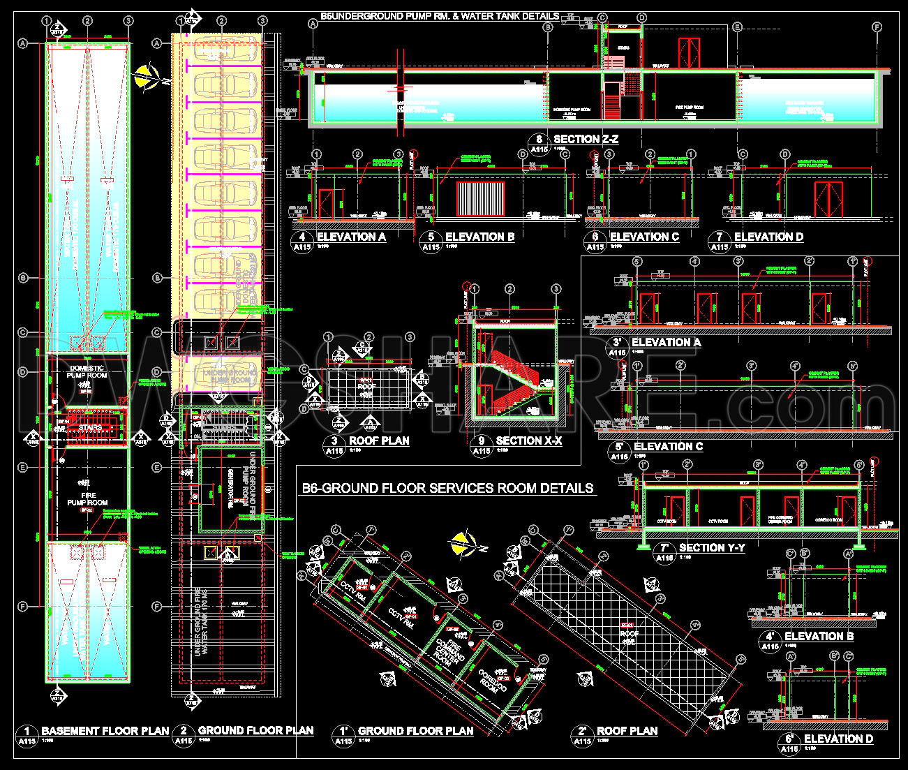
762. Ready to Use Underground Water Tank and Pump Station CAD Details DWG
The Ready to Use Underground Water Tank and Pump Station CAD Details DWG serves as an invaluable design resource within architectural and construction practices. This comprehensive CAD drawing focuses on essential components required for the efficient planning and execution of underground water storage solutions. The file includes precise architectural floor plans, detailed elevations, and comprehensive sections, all critical for effective project development and execution.
In the initial segment of the drawing, the basement floor plan and ground floor plan are meticulously outlined. This section showcases the strategic layout of pump rooms, designed to optimize space and ensure seamless operation. Each level is clearly annotated with grid lines and dimensions, essential for architectural precision and aiding construction teams in accuracy during implementation.
Complementing the floor plans, the detailed elevations contribute significantly to the visualization process. Featured elevations, labeled A through D, present the vertical alignment of structural components, facilitating a deeper understanding of spatial relationships and material finishes. This inclusion is vital for architects and construction professionals handling the practical application of materials and design elements.
The drawing also meticulously delineates sections such as Section Z-Z and Section X-X. These sections provide a cut-through view of the underground structures, offering insights into depths, heights, and functional zoning. The sections are indispensable in revealing the tank’s internal mechanics and ensuring that every component aligns with design specifications.
Leveraging the CAD format enhances the technical proficiency of the drawing. With high precision and accuracy, the DWG files are easily modifiable, enabling architects and engineers to tailor the plans to their specific project needs. This adaptability not only improves project coordination but also reduces potential construction errors, ultimately contributing to cost savings.
The drawing details are made available free of charge, promoting their use as a design reference or educational tool. Students, designers, and professionals can utilize these files for study, research, and as a foundational base for developing their technical drawings, fostering an informed approach to designing robust underground water systems.
By providing detailed, technically accurate CAD files, this resource encourages streamlined collaboration between design and construction teams, ensuring a high level of precision and efficiency in both design development and on-site execution.
I also recommend downloading other Cad Details CAD drawings for your project reference.
- File format: .DWG
- Size: 1 MB
- Source: DWGshare
- AutoCAD platform 2018 and later versions. For downloading files there is no need to go through the registration process
If you find our work useful, your support would mean a lot and help us grow even better.DONATE
Related posts
118.Autocad Drawing Of Concrete Cascading Raised Planters For Download
204.Structural Drawings Of 4-Story House A Complete Project 12.3×16.7m For Download
341. Free Download of Structural CAD Drawings for 5m x 23m Reinforced Concrete Townhouse
615. Cantilever Wall Reinforcement CAD Details Free Download
42.Typical Welding Details Single Bevel for HMW CAD
733. Concrete Staircase Reinforcement Details CAD Drawings DWG
680. CAD DWG Template – Keystone Retaining Wall Structural Details
402. Free Download of Structural CAD Drawings for 10.4m x 11.5m Reinforced Concrete Townhouse
125.Autocad Drawing Of Cast In Place Concrete On Slab For Download