
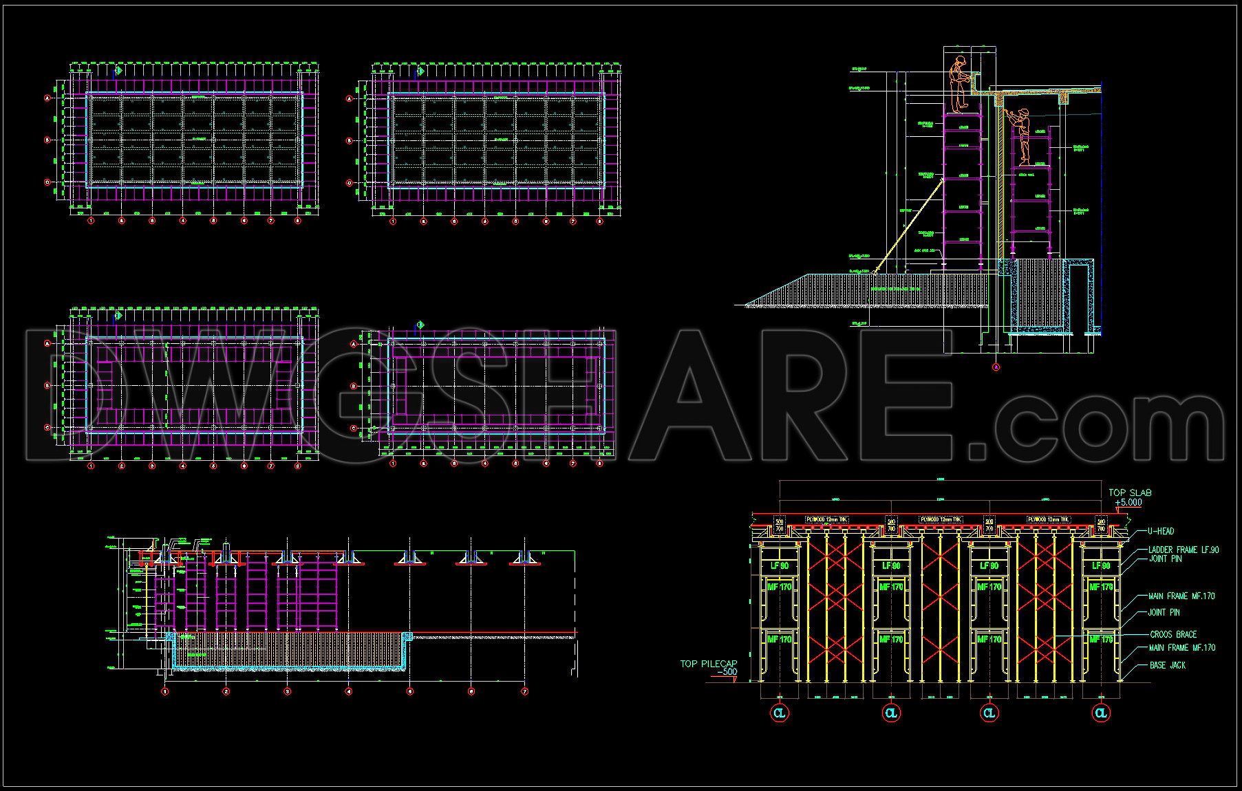
773. External Scaffolding Details CAD Drawing – Complete Construction DWG
The external scaffolding details CAD drawing presented in this file is an invaluable resource for architects and construction professionals focusing on the intricacies of erection and safety planning. As a structural drawing, it offers a comprehensive visualization essential for both design development and on-site implementation. This detailed document specifically highlights the alignment and arrangement of scaffolding components, serving as a backbone for efficient construction coordination.
The primary elements visible in this drawing include:
Precise elevation and section views
Comprehensive grid lines and level markers for accuracy
Component specifications, including ladder frames, joint pins, and cross braces
Detailed plan layouts illustrating scaffold positioning
The role of these elements is significant in real construction practices. Elevation and section views provide clear visual insights into the vertical and horizontal alignment of scaffolding, crucial for ensuring structural integrity and safety. The grid lines and level markers aid in precise location and height assessment, critical for maintaining stability and complying with regulatory standards.
For architects, this structural drawing is pivotal during the design development phase as it facilitates accurate planning and specification of scaffolding requirements. Interior designers may reference these details when integrating temporary structures within complex projects to ensure seamless design continuity. Construction teams benefit immensely from this resource, as it offers a reliable reference for scaffold assembly, enabling efficient teamwork and minimizing the risk of errors.
The practical value of this CAD file is underscored by its high technical accuracy and ease of modification in AutoCAD. These features are essential for reducing planning errors, optimizing costs, and enhancing coordination between design and construction phases. Furthermore, sharing these CAD DWG files for free is a boon for professionals and students alike, offering opportunities for design reference, study, and as a foundational base for advanced technical drawing development.
In summary, this external scaffolding details CAD drawing serves as an essential tool for optimizing construction workflow and ensuring robust safety standards. Its detailed layout and comprehensive component specifications make it a go-to resource for enhancing efficiency and precision in construction projects.
I also recommend downloading other CAD drawings for your project reference.
- File format: .DWG
- Size: 1 MB
- Source: DWGshare
- AutoCAD platform 2018 and later versions. For downloading files there is no need to go through the registration process
If you find our work useful, your support would mean a lot and help us grow even better.DONATE
Related posts
707. Raft Foundation Layout Design – Free AutoCAD Drawing Download
443. Download Free Detailed CAD Drawings of Raft Foundation Steel Structure Plans
354. Free Download of Structural CAD Drawings for 9.8m x 13m Reinforced Concrete Townhouse
202. CAD drawing Of Bunglaw Foundation template Free download
289. Structural Drawings Of 3-Story House A Complete Project 3.9m x 7.6m For Download
47.Side Walls Elevation and Bracing Details CAD
298. Structural Drawings Of 3-Story House A Complete Project 7m x 14.7m For Download
704. Free Download Pre-Tension Beam Reinforcement Details CAD
296. Structural Drawings Of 2-Story House A Complete Project 4m x 15m For Download