
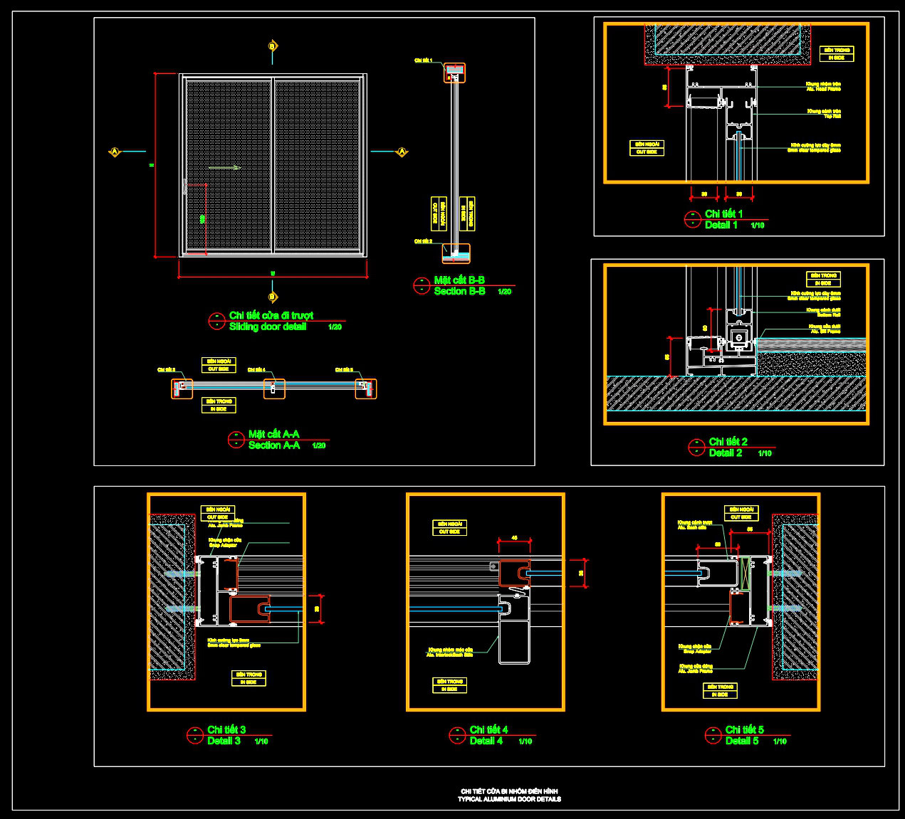
885. Typical Aluminium Sliding Door Details CAD Drawing (DWG)
The typical aluminium sliding door details CAD drawing offers an insightful exploration into the structural intricacies of modern sliding doors, ideal for architects and construction professionals. This detailed drawing provides valuable architectural detail drawings that showcase significant elements such as the main elevation view, essential cross-sections, and meticulous alignment guides.
Key components featured in this technical drawing include:
– Functional elevation view that illustrates the overall design and placement within a project, essential for visualizing the aesthetics and alignment with broader architectural plans.
– Section A-A and Section B-B providing critical cross-sectional views, revealing the internal mechanics and alignments, indispensable for ensuring the accuracy and integrity during installation.
– Detailed component drawings, highlighting specific elements like door jambs, threshold details, and frame connections. These are pivotal for precision in manufacturing and installation.
– Grid lines, dimensions, and level markers enhancing comprehension and application, allowing for precise and error-free execution in the field.
The architectural detail drawings serve a fundamental role within design documentation and practical construction. For architects, these drawings facilitate the comprehensive design development process, offering clarity on component integration and overall structural coherence. Interior designers benefit by using these technical details to ensure seamless integration with interior elements, enhancing both functionality and aesthetic appeal.
For construction teams, these drawings act as a critical reference point, ensuring accurate implementation and cohesion between design intent and tangible outcomes. The precision offered in these CAD drawings translates to reduced errors, optimized costs, and a robust framework for any sliding door installation project.
The practical value of these CAD drawings lies in their high technical accuracy and adaptability. Easily modifiable and reusable in AutoCAD, these drawings ensure improved coordination between design and construction teams. Architects and designers can modify these templates to suit specific project needs, supporting efficient and error-free design progression.
These CAD DWG files are shared for free, making them an ideal resource for design reference, academic study, or as a foundational base for developing technical drawings. Utilization of these detailed drawings underscores a commitment to innovative yet practical design and construction execution.
I also recommend downloading other Door CAD drawings for your project reference.
- File format: .DWG
- Size: 233 KB
- Source: DWGshare
- AutoCAD platform 2018 and later versions. For downloading files there is no need to go through the registration process
If you find our work useful, your support would mean a lot and help us grow even better.DONATE
Related posts
777. Free Download – Fire-Rated Doors, Glass Doors and Window CAD Drawings
490. Detailed CAD Drawings Of Doors, Windows For Download
662. Free Download of Detailed Door and Window Drawings in European Classical Style
501. Detailed CAD Drawings Of Doors, Windows For Download
255. Autocad Wooden Door free download
430.Detailed AutoCAD Drawings Of Doors, Windows For Download
320. Autocad wood – glass doors free download
832. Free Download CAD Drawings of Sliding Doors (uPVC & Wooden)
769. Download Free DWG CAD Details of Doors and Windows