
174. Residential MEP Plumbing CAD Drawings – Water Supply, Drainage and Septic Tank System
The residential MEP plumbing CAD drawings provided cover an intricate and essential part of construction planning, focusing on water supply, drainage, and the septic tank system. These drawings are a fundamental tool used extensively in the architectural and construction fields to ensure precise planning and execution of plumbing systems within residential projects.
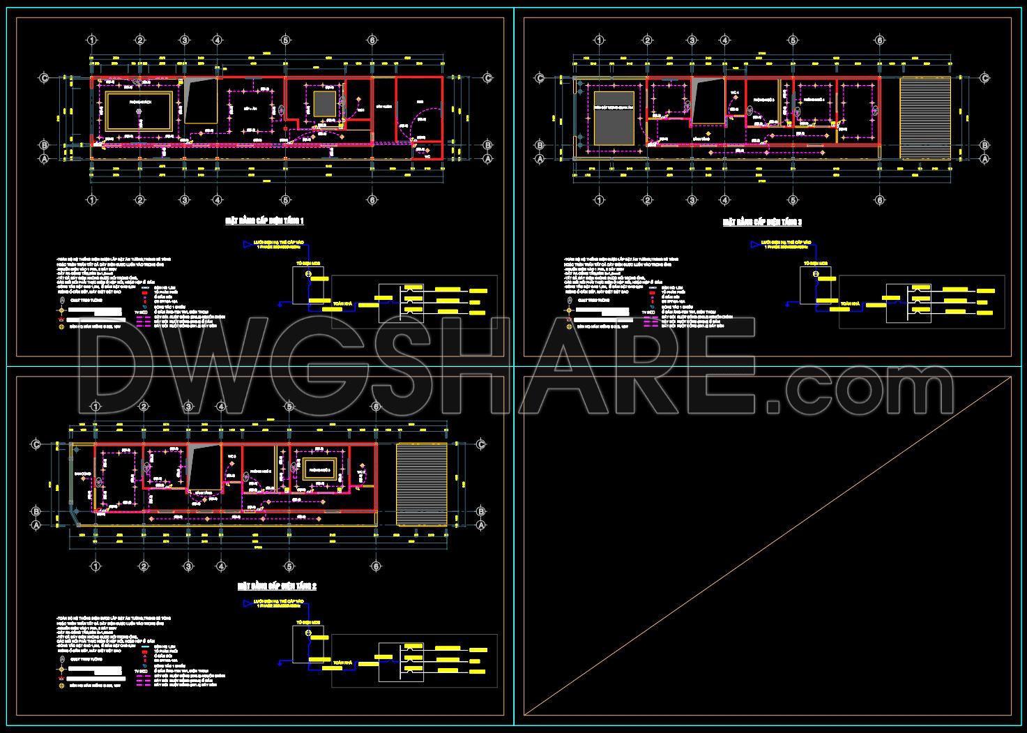
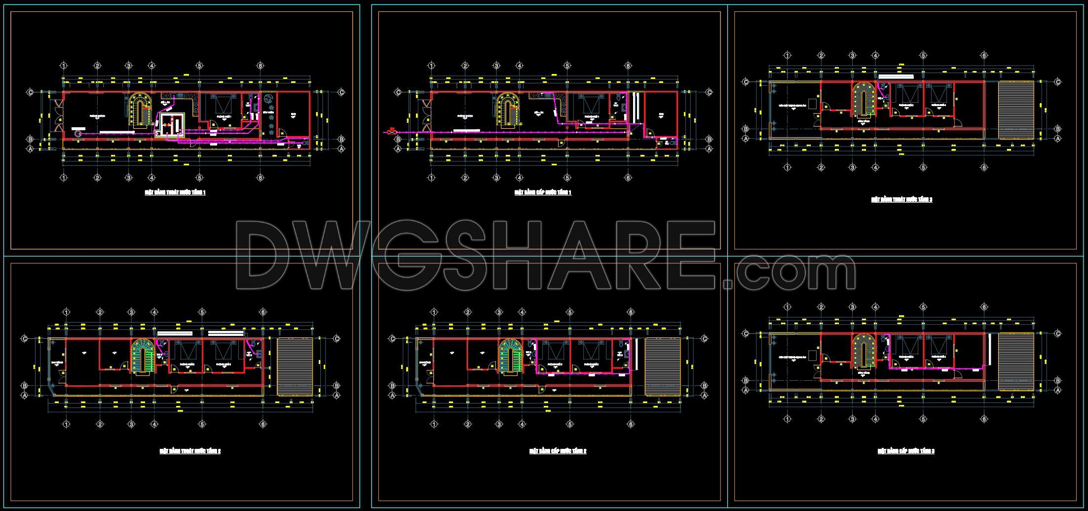
The main objective of these plumbing CAD drawings is to illustrate the detailed layout and components concerning the water supply and drainage systems. These drawings include multiple viewpoints and detailed annotations that cater to various professional needs. The inclusion of functional floor plan layouts is crucial, providing a clear overview of how plumbing lines run through different areas, ensuring efficient water flow and optimal placement within the building layout.
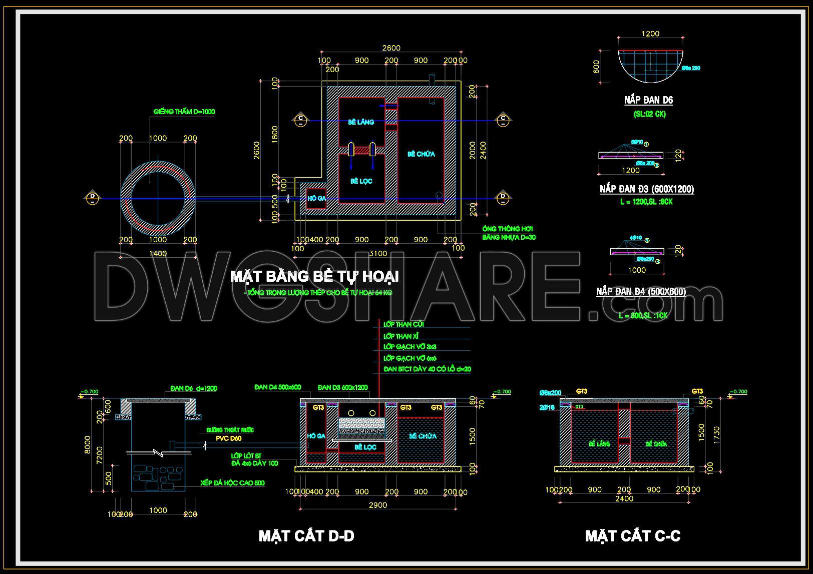
Moreover, these plans encompass detailed construction drawings of the septic tank system. Highlighted elements include the plan layout of the septic system, denoting compartments like the filter chambers and holding tanks. This level of detail is invaluable for ensuring compliance with health and safety standards, which is paramount in residential construction. Technical aspects like grid lines, dimensions, and level markers are meticulously noted to guide installation with precision.
In practice, these CAD drawings serve several vital roles. Architects use them during the design development phase to ensure all plumbing components are exactly where they need to be. For interior designers, access to these detailed layouts allows for the seamless integration of fixtures and fittings, aligning with aesthetic and functional goals. Construction teams rely heavily on these drawings for reference and coordination, minimizing errors, thereby enhancing the efficiency of onsite work.
The practical value of highly accurate CAD drawings cannot be overstated. The option for easy modification and reuse is a standout feature, particularly for professionals using AutoCAD software. This versatility leads to improved coordination between design and construction phases, ultimately optimizing costs and reducing potential errors.
These free-to-access CAD DWG files are not only an excellent resource for design reference but also provide opportunities for study and research. Whether it’s used as a base for developing technical drawing skills or for exploring new design possibilities, the availability of these files is a valuable asset for professionals in architecture and construction.
I also recommend downloading other Mechanical, Electrical CAD drawings for your project reference.
- File format: .DWG
- Size: 1 MB
- Source: DWGshare
- AutoCAD platform 2018 and later versions. For downloading files there is no need to go through the registration process
If you find our work useful, your support would mean a lot and help us grow even better.DONATE
Related posts
76. Free Download CAD Drawings of Water Pump Control Panel – Electrical Schematic and Cabinet Layout
197. House Water Supply and Drainage CAD Drawings – Complete Plumbing Plans
11.Earthing and Lightning Layout Plan CAD
195. Complete Residential Water Supply and Drainage System CAD Drawings DWG
340. Free Download of Mechanical and Electrical Construction Design Drawings for a 3-Story House
14.Guard Room Lighting and Power Plan CAD
173. Plumbing System Design DWG for 3-Storey House
274. Complete House Plumbing Plans – Water Supply & Drainage System DWG
76. CAD drawings detailing the design of water supply and drainage systems for a 3-story townhouse