

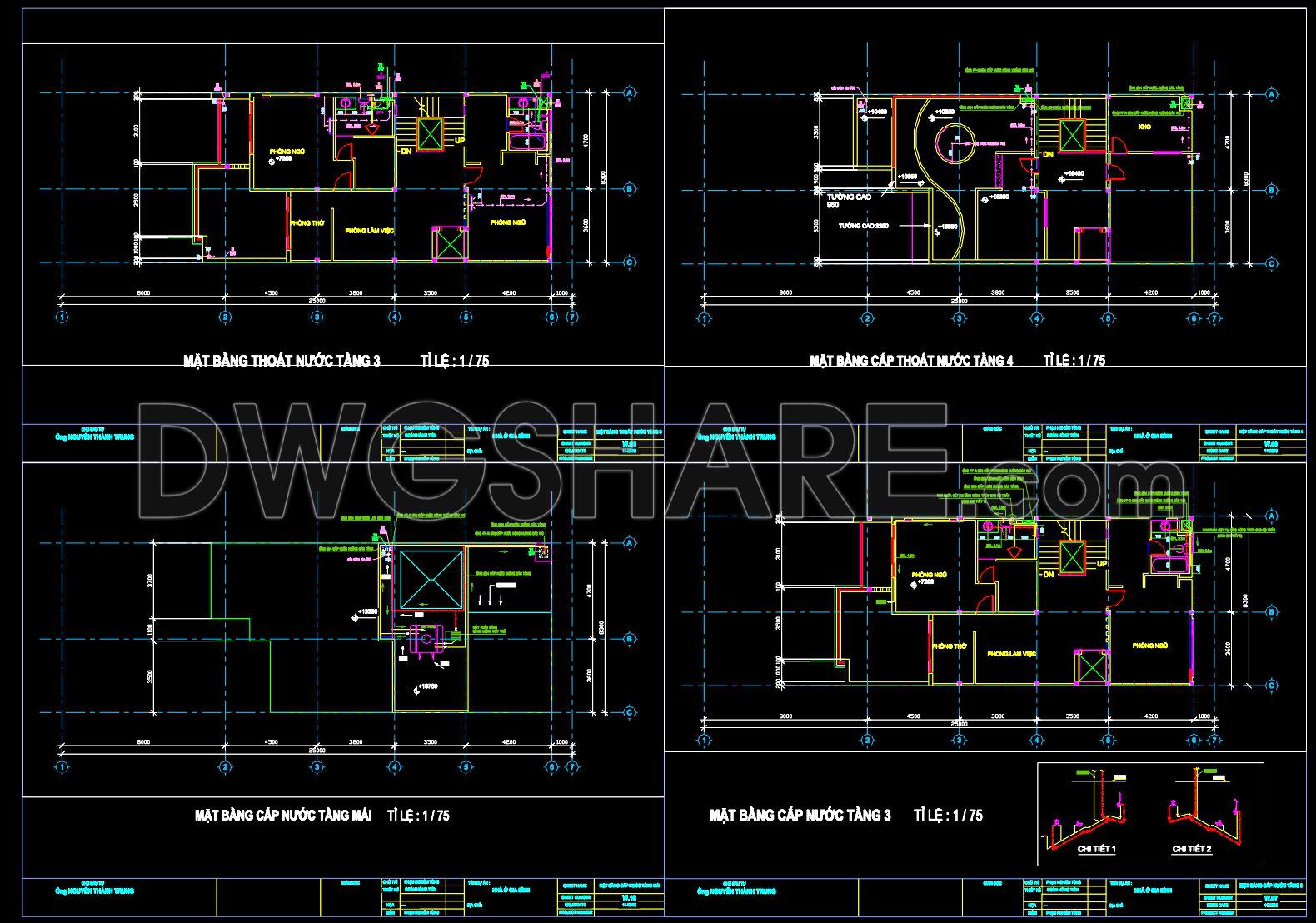
180. Plumbing CAD Drawings DWG – Water Supply & Drainage System
These Plumbing CAD Drawings DWG files are invaluable resources for architects, interior designers, and construction professionals focusing on water supply and drainage systems. The drawings predominantly feature functional floor plan layouts for multiple building levels, each rendered with technical precision to ensure accurate interpretation.
Among the essential components visible in these CAD files are:
Detailed water supply systems
Comprehensive drainage layouts
Clearly marked grid lines
Precise dimensions and level markers
Each drawing caters to the critical needs of architectural design and construction documentation. The functional floor plan layout offers a thorough view of the building’s water systems, allowing architects to plan and coordinate effectively. These plans play a vital role during the design development phase, enabling architects to visualize and adjust designs in a digital environment before implementation.
Specific layers in these CAD drawings outline the routing of pipes and drainage channels. This information is crucial for construction teams for reference and coordination, ensuring that the intended design is translated into reality efficiently and without errors. The inclusion of grid lines, dimensions, and level markers simplifies the task of verifying site conditions against drawn plans, a vital step in preventing costly mistakes during the construction phase.
Construction teams can utilize these detailed drawings in multiple ways. They provide a blueprint for accurate installations and adjustments, reducing the risk of misalignment and subsequent rework. This aids in maintaining the project’s budget and scheduling constraints, offering a seamless pathway from drawing interpretation to project completion.
Furthermore, the utility of these CAD files extends to the realm of interior design. Interior designers can extract pertinent technical details from these plans to refine their spatial layouts, ensuring all water connections and systems integrate seamlessly with the overall aesthetic and functional design.
An added benefit of these drawings is their high technical accuracy and easy modification capabilities within AutoCAD, which fosters improved coordination and communication between design and construction teams. The DWG format allows for adaptable use in varied projects, thus optimizing costs and reducing potential errors.
The CAD DWG files are shared for free, making them an excellent resource for design reference, study, and further technical drawing development. Availability in this format encourages widespread use among professionals seeking reliable and comprehensive resources to guide their water system planning.
I also recommend downloading other Mechanical, Electrical CAD drawings for your project reference.
- File format: .DWG
- Size: 1 MB
- Source: DWGshare
- AutoCAD platform 2018 and later versions. For downloading files there is no need to go through the registration process
If you find our work useful, your support would mean a lot and help us grow even better.DONATE
Related posts
507. Free Download High-Rise Apartment Fire Protection CAD Drawings
219. Download Complete Plumbing CAD Drawings for House – Water Supply & Drainage
48. The detailed CAD drawing of a septic tank.
162. Complete Residential Water Supply and Drainage System CAD Drawings DWG
53. CAD drawings detailing the design of water supply and drainage systems for a 5-story townhouse 6.8m x 13.8m
216. Download Complete House Electrical CAD Drawings – Lighting & Power Plans
327. Stairwell Pressurization System with Fan, Ductwork and Control Diagram CAD Drawings
4. Electrical Lighting Cad Blocks free download
159. 2-Storey House Electrical System CAD Drawing Download