
461. Residential Building Structural CAD Drawings – Plans, Reinforcement & Details
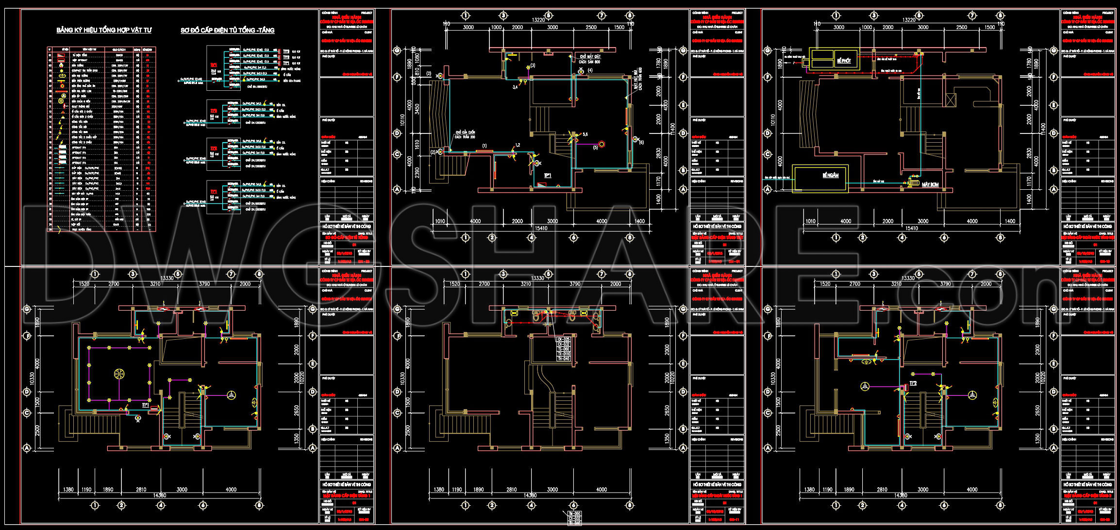
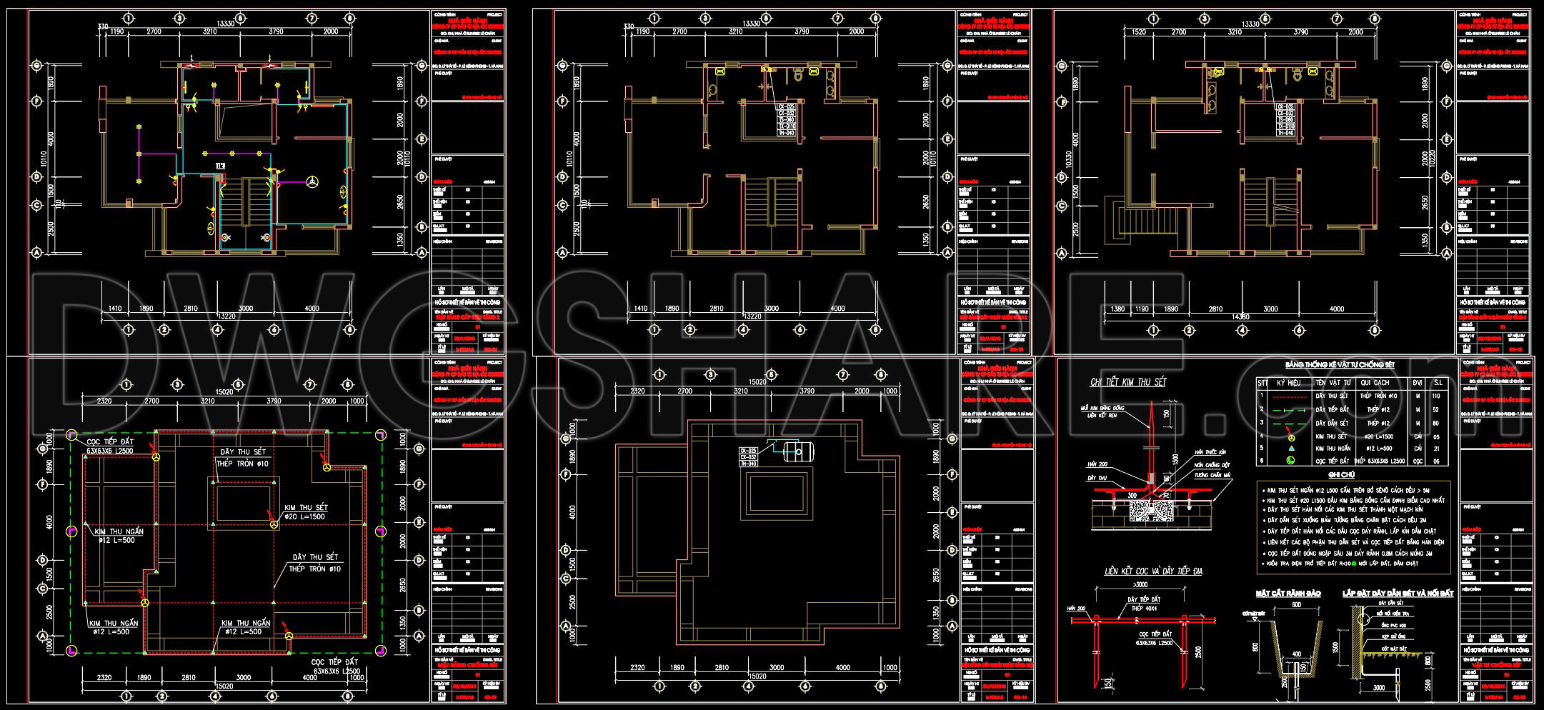
The Residential Building Structural CAD Drawings showcased in these CAD files serve as an invaluable resource for professionals in architecture and construction. The drawings primarily encompass structural plans, meticulously detailing the building’s framework to ensure the structural integrity of residential projects. Key aspects include floor plan layouts, reinforcement details, and construction sections, each serving distinct yet complementary roles in the architectural design process.
Beginning with the floor plan layouts, these drawings portray a comprehensive blueprint of the building’s structural framework. Emphasizing utility, they incorporate precise metric measurements along with clear grid lines that delineate individual rooms and spaces. This precision facilitates architects in the design development phase, where accuracy and detail are paramount. The floor plans are organized logically, enhancing easy interpretation for both interior designers and construction teams, enabling them to adapt spaces according to functional needs.
Next are the reinforcement details, which are critical for structural engineers. Here, specifics of reinforcements such as types of steel rebars, diameters, and placement are defined with exacting precision. This meticulous detailing assures that structural elements can withstand both expected and unforeseen stresses, pivotal during the construction phase to prevent structural failures. These drawings are essential for construction teams, providing a clear directive for on-site execution and reinforcing safety standards throughout the building process.
In addition to reinforcement details, the construction sections deliver a three-dimensional perspective, illustrating various aspects of the building’s construction. This involves a detailed breakdown of vertical and horizontal sections across different building components, aiding in understanding how elements come together in real-world application. Sections clarify complex aspects such as cross-sectional dimensions, ensuring that all team members have a unified, coherent understanding of how the layers of the building interrelate.
From a practical perspective, these CAD drawings stand out due to their high technical accuracy and adaptability. Being easily modifiable in AutoCAD, they aid architects and engineers in iterative design processes, allowing swift adaptations and corrections, thereby significantly reducing potential for errors. The availability of these files for free enhances their utility, making them an excellent base for technical drawing development as well as a rich resource for students and professionals seeking design reference or study material.
I also recommend downloading other Buildings CAD drawings for your project reference.
- File format: .DWG
- Size: 497 KB
- Source: DWGshare
- AutoCAD platform 2018 and later versions. For downloading files there is no need to go through the registration process
If you find our work useful, your support would mean a lot and help us grow even better.DONATE
Related posts
17.Dining Hall Steel Structural Layout and Sections Details CAD
770. Complete Water Tank Sections CAD Template DWG
227. Structural Drawings Of 3-Story House A Complete Project 5.8mx17.1m For Download
55.Steel Girder AutoCAD File Free Download
766. Full Water Fountain Section Details CAD DWG Download
124.Autocad Drawing Of Cast in Place Concrete With Brick Band Details For Download
8.Structural steel connections Autocad Drawing Free Download
96.Autocad Drawing Of Classrooms Structural and Electrical Details For Download
245. Structural Drawings Of 6-Story House A Complete Project 10m x 19.5m For Download