
519. Electrical Power Layout Plans – Ground and Second Floor CAD Drawings
The Electrical Power Layout Plans for the ground and second floors presented here are a cornerstone in architectural design and construction execution. These CAD drawings are essential as they provide comprehensive plans for electrical installations across two critical building levels. Serving as a vital resource, these plans ensure that electrical systems are meticulously integrated with the structural design, enabling seamless construction and future modifications.
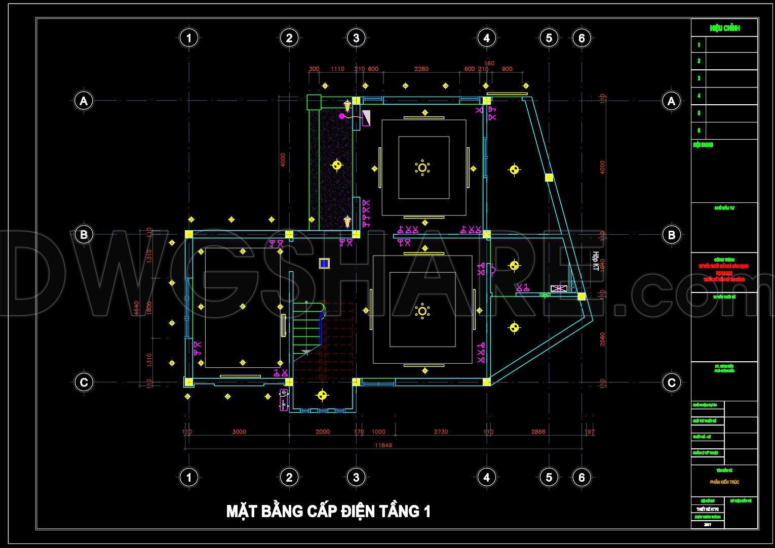
Starting with the ground floor, the CAD drawing meticulously illustrates the functional floor plan layout with precise positioning of electrical components to guarantee efficiency and safety. Important elements such as grid lines, dimensions, and level markers are clearly defined, proving invaluable for architects during the design development phase. These markers not only guide the accurate placement of electrical fixtures but also aid in aligning the design with other structural components.
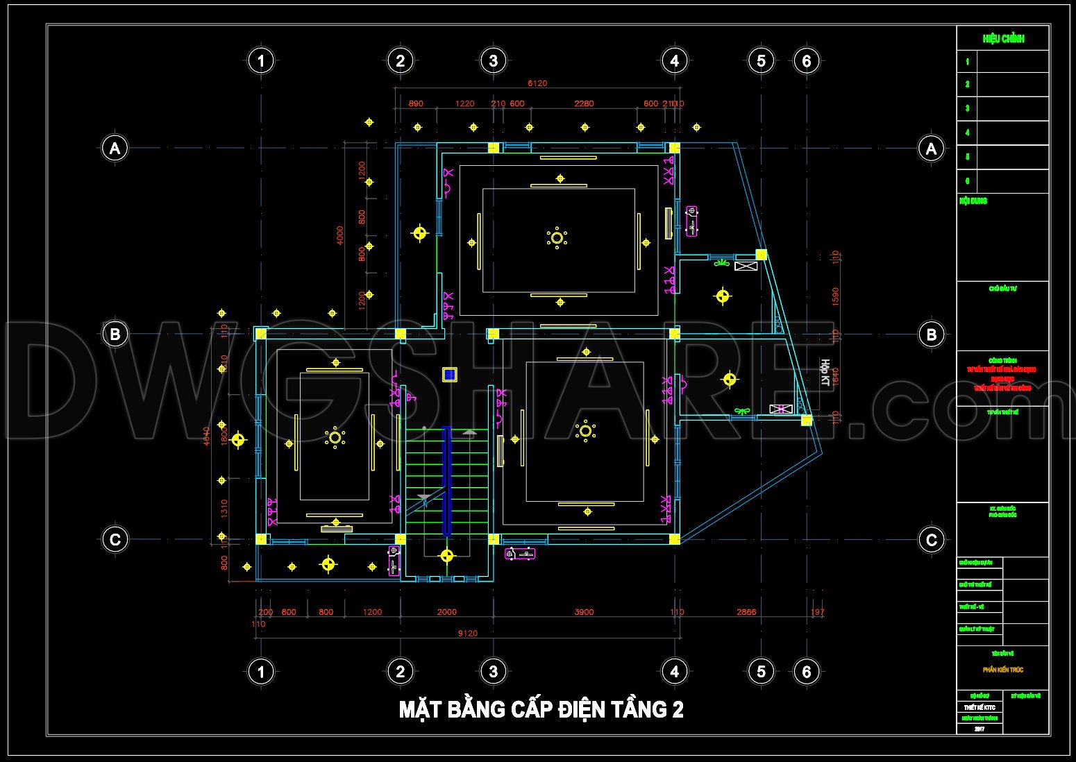
Moving to the second floor plan, the drawing continues to focus on exactitude, featuring detailed construction or furniture elements, enhancing clarity for construction teams. The layout details the strategic positioning of lighting fixtures and power outlets, critical for adherence to building codes and ensuring optimal functionality. These plans are crafted to accommodate easy access to electrical systems for future maintenance, thus bolstering the building’s long-term viability.
Electricians and construction teams rely heavily on these drawings to execute installations flawlessly. The technical precision and clarity within these documents facilitate improved coordination between the various teams involved, reducing errors and potential rework costs. Moreover, the drawings’ AutoCAD format allows for easy modifications, essential for adapting to on-site changes or client requests.
These CAD DWG files are shared openly for purposes such as design reference or study and research, providing a solid foundation for technical drawing development. They offer invaluable insights for those learning about electrical layout planning and its integration into comprehensive building designs. The ability to modify and reuse these drawings enhances collaborative efforts, fostering innovation within the architectural and construction communities.
In conclusion, these electrical power layout plans serve as a vital tool in ensuring successful project delivery. By integrating high technical accuracy with practical usability, they contribute significantly to cost optimization and effective construction management.
I also recommend downloading other Mechanical, Electrical CAD drawings for your project reference.
- File format: .DWG
- Size: 139 KB
- Source: DWGshare
- AutoCAD platform 2018 and later versions. For downloading files there is no need to go through the registration process
If you find our work useful, your support would mean a lot and help us grow even better.DONATE
Related posts
185. Complete Residential Electrical, Lighting and Communication System CAD Drawings DWG
62. Detailed CAD design drawings for the water supply system in a 5-story townhouse
282. Residential Plumbing Plans – Water Supply, Drainage & Rainwater System DWG
162. Complete Residential Water Supply and Drainage System CAD Drawings DWG
46. CAD drawings for detailed plumbing designs for a 4-story townhouse with dimensions of 8m x 17m
262. Residential MEP Design Plans – Electrical, Plumbing, HVAC & Low Voltage CAD Drawings
176. Complete House MEP CAD Drawings – Electrical, Lighting, Water Supply and Drainage Design
179. Complete Residential Electrical, Lighting and Communication System CAD Drawings DWG
254. 3-Story House Plumbing Plans – Water Supply & Drainage System CAD Drawings